Seeking help with a ring artifact

deletio

Member
Greetings.

I wasted a whole winter jumping from one hypothesis to another regarding possible cause of the ring artifact in my stacks. Yesterday yet another theory fell apart and I decided to try and reach out for help.

Some basic data to begin with. I'm trying to shoot mono with a refractor reduced to 700mm F/5.5 from a Bortle 8/9 zone in the middle of Tokyo.
I started seeing The Ring in my stacks having switched from a narrowband target to M45, but after many futile attempts at troubleshooting I have actually confirmed it is actually present in narrowband stacks as well.

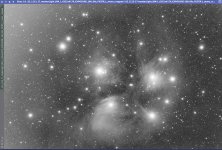
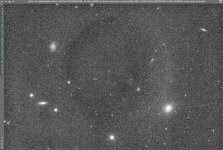
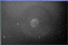
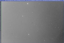
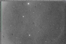
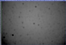
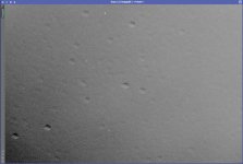
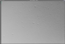
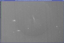
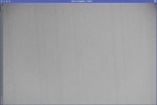
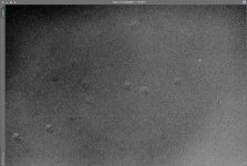
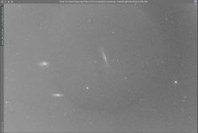
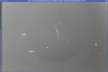
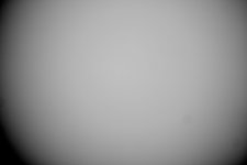
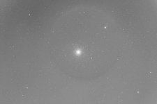
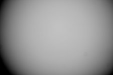
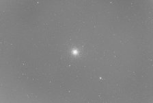
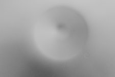
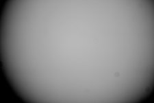
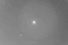
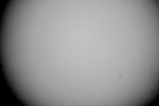
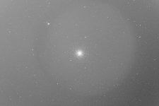
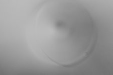
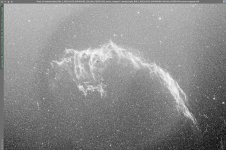
Here are some examples merely stretched to extremities for the sake of displaying the subject Ring, otherwise directly out of WBPP:
OIII: Veil_OIII_Ring.jpg L: M45_L_Ring.jpg R: M49_R_Ring.jpg Ha: Abell31_Ha_Ring.jpg
  • I experimented with ambient light on the balcony
  • I have checked the imaging train for light leaks, it is sealed
  • I have spray-painted the glossy adapters matte black
  • I have checked the flats for unevenness, which didn't look too bad (under 2%)
  • I tried taking different sets of flats with different positions of the flat panel. The Ring was still there regardless of which set was used for calibration, as well as when all sets were averaged together. The resulting artifacts were exactly the same, which I confirmed by using PixelMath.
While the artifacts shines in full glory in stacked images, I was able to stretch calibrated subs and locate the Ring in each of them, although a much more subtle version of it.

I suppose it is worth mentioning that I cannot see the Ring in uncalibrated subs or in stacks without flats. There are just too many dust motes and really strong vignetting. This is to say that my flats do seem to do their job fine.

Having just posted these 4 examples I could not help noticing that the ring changed its size. The OIII image was taken last fall, the L stack is from some time in winter, while R and Ha are rather fresh, taken after painting the adapters matte black. So could it be that the QHY spacers that "sit" between the OAG and the camera keep producing the reflection, and the size of the artifact has gotten smaller because I matte-painted the adapters further away from the sensor? Does this sound reasonable?

If there are any other guesses or suggestions, I would love to consider them. Also will happily share data from one of the sessions if somebody is willing to dig through.

Thank you!
 
This effect is the perfect signature of a corrector lens. Having a corrector requires that you have parallel incoming light rays which are devilishly difficult to reproduce when using a light panel which scatters light (and the incoming light is at random angles).

The change in size of the artifact tracks with changes in spacing with respect to the corrector lens. Again, am I wrong? For all of the theories you heard did they talk about this?

So what is the solution? Diagnostically you can use night sky flats to prove to yourself that your panel created flats are illuminating your sensor (because of the corrector) differently then when light from the sky falls on the sensor. You can also (but I do not recommend it unless it is easy to do) remove the corrector and verify your flats work nicely without its presence.

I explain night sky flats in my content on my site:

-adam
 
i've had the same problem with a reflector, both with and without a reducer.

without the reducer installed, the problem was reflections in the focuser drawtube, and i think i was also getting off-axis light reflecting off other parts of the focuser ahead of the drawtube. ironically, removing the reducer exposed parts of the focuser drawtube that were not visible to the camera when the reducer was in place, and so the problem only appeared *after* removing the reducer. flocking all of that shiny stuff in the focuser drawtube and beyond fixed the problem. like you it was really only visible in RGBL images, not narrowband. but it sounds like you've taken care of that.

there's a thread on CN, which is about a reflector, but it turned out using any adapter or other equipment that had a diameter less than M48 was causing similar rings. the camera in question was a 2600MM with a 48mm opening on the OAG.

i think adam's suggestions are good - you can also take regular old sky flats and calibrate your panel flats with the sky flats and see if you get the artifact. that will tell you for sure that the panel flats don't illuminate the sensor the same way as the night sky.

rob
 
Thank you very much for the suggestions gentlemen.

@ngc1535
This is a terrible news indeed, but unfortunately your explanation perfectly matches my situation: last year I was using an incorrectly calculated backfocus and placing the sensor farther from the sensor than it is now.

What is hard for me to grasp is that my reducer is the last FC-35 offering by Takahashi, which I expect to be used by many astrophotographers, and yet I could barely find any reports of similar artifacts, let along with this specific reducer (none). It must be the combination with my outdated OTA (FS-128) that is actually problematic. Indeed, I have seen literally nobody online using this combination. Anyway, it is not a problem at all to remove the reducer and shoot a test without it. In fact, I install and remove it every session anyways.

I suppose one approach to try could be to find the old-school reducer made specifically for FS-102/128 OTAs and see if it performs better. I actually had it before, but upgraded to the newer and faster one together with the camera. They do appear in the secondary market here in Japan once in a while. While not as fast at F6 as FC-35, I will be happy to downgrade if it helps with the Ring.

What will be a major issue though is shooting night sky flats with narrowband filters. Maybe for a permanent setup it would be OK to just wait until dawn, but since I wrap up every time at 1am max it's not an option at all. Do you happen to know of any other solutions that would be applicable to both using reducers producing this effect and narrowband filters? Please do not say upgrade to a newer OTA (of course do if that's the only option).

@pfile
I have not flocked any parts of the OTA myself, but rather looked inside to confirm it was rather good by itself. I tried additional flocked dew shields, but they produced no improvements. And the Ring is visible in all filters in my case. Further, my camera has the same sensor as what you said was mentioned in that CN thread, but my adapters/spacers are all 54mm wide.

I will try the night sky flats, but I can't understand how that method could be used with narrowband.

— Kirill
 
Thank you very much for the suggestions gentlemen.

@ngc1535


I will try the night sky flats, but I can't understand how that method could be used with narrowband.

— Kirill
It is true. True night sky flats will not work with NB. You simply cannot get the sky bright enough.
Twilight flats might help... but I have not found that they do in my experience. Again, too many off-axis photons running around.

-adam
 
It is true. True night sky flats will not work with NB. You simply cannot get the sky bright enough.
Twilight flats might help... but I have not found that they do in my experience. Again, too many off-axis photons running around.

-adam
There is no difference between a night flat and a twilight flat in terms of where photons are coming from! Either source has the same radiation pattern.
 
since regular sky flats are easier, you might try with those first. even if they don't correct the lights properly you might see a difference from the panel flats when dividing the panel flat into the sky flat and that is a hint that the panel flats don't illuminate the sensor the same way the sky does.

rob
 
One thing to try is to reduce the target ADU for the flats. I was plagued by a ring when I targeting an ADU of 32768. I reduced this to 1200 and the flats are perfect and the ring much much reduced.
I think that by using a high light value for the flats, increases the likelihood log reflections.
It worked for me.
Tom
 
Hi,
May I ask what are the exposure times of your flats?
Perhaps you exposure times are too short?
I am no expert but you could try using some layers of vellum paper in order to increase your exposures times. Just an idea...
 
Again, thank you all for chipping in with your ideas, they are invaluable!
I have not yet arrived to any conclusive results, but two attempts have been taken, which I will outline below.

  • 60 x 60s L subs (which I now realize was excessive for the purpose) of the sky that was pretty much right West of the meridian in the South as that's where the system was pointed for drift alignment
  • 2 sets of 60 flats by 1.1s with the flat panel in mutually perpendicular positions
  • 60 bias frames
Thoughts on results:​
  • The first thing that jumps at me when I look at the master light is that there are some uncalibrated dust motes, which has never really been an issue for me. However, just before creating this thread, the last theory I was going through was about the flat panel being badly positioned in a way such that its edge was in the FOV thus ruining the sensor illumination evenness. I ended up disassembling the flat box and essentially extracting the bare panel. So now — without the box — I had to point the telescope to the zenith in order to put the panel on top of the dew shield. And I'm thinking this could make some dust fall onto the lens before the flats were taken.
  • I was going to say the Ring was not visible and it was very tempting to just declare the reducer the culprit, but one alternative explanation that I wanted to consider was that the Ring could really still be there, but just outside of the non-reduced FOV. In fact, some kind of an arc is clearly visible on the right, especially before applying gradient correction. But after GC and with a good stretch it totally looks like a Ring, doesn't it?
Master light before any correction:
1-f8-masterlight-juststretch.jpg
Master light gradient-corrected with default GC settings and extremely stretched:​
2-f8-masterlight-gc-stretched.jpg
Master flat of one of the 2 sets (I have already bought a lens cleaning kit):​
3-f8-masterflat.jpg
Difference in master lights (calibrated with the different sets of flats), as in A + mean(B) - B:​
4-f8-masterlight-diff.jpg
Difference in master flats, as in A * mean(B) / B looks pretty much like an inverted difference in lights, which could probably be shown on paper:
5-f8-masterflat-diff.jpg
  • 15 x 60s L subs again just West of the meridian in the South, but this time on a proper target
  • Set #1 of 30 x 0.33s flats with the flat panel with its set of 30 x 0.33s darks
  • Set #2 of 30 x 6.3s flats for the sake of extending the exposure time with the flat panel dimmed by sheets of paper — also with its set of 30 x 6.3s darks
  • 60 bias frames
  • For sky flats I ended up settling on 30 x 60s, their mean values ranging merely from 3900 to 4200. To integrate them I
    • First used this tutorial by Vicent Peris as reference on calibration/integration parameters and then loaded the resulting master in WBPP. In particular,
      1. They were calibrated by master bias and the 6.3s master dark with the "optimize" option enabled
      2. Somehow using darks in this process still left hot pixels in the stack, so I ended up applying Cosmetic Correction at this stage
      3. Average-integration with multiplicative normalization and percentile clipping of 0.01 set as the value on both ends
    • Then also tried just loading all of them as flats directly in WBPP and setting the flat integration parameters to average-integration with multiplicative normalization and percentile clipping of 0.01 on both ends therein (no optimized dark was used in this approach)
Results:​
  • The WBPP-integrated sky flats ended up producing a cleaner result than with manual approach, but regardless of that: these sky flats did not remove the Ring:
    6-sky-flats-master-light.jpg
  • In fact, calibrating the panel-acquired master flat by the WBPP-integrated master sky (A * mean(B) / B) flat produced no visible indication of the source of the Ring. Merely traces of rejected star trails:
    7-panel-flat-by-sky.jpg
  • Comparison by subtraction (A + mean(B) - B) of the 2 panel-based master flats (0.33s vs 6.3s subs) when gradient-corrected with scale 8 / smoothness 0.8 and stretched to extremities actually shows some circular pattern:
    8-box-flats-compared.jpg
  • However, there's not much difference in master light stacks calibrated by these different master flats, and both show the Ring in its full glory:
    9-0.33-flats-master-light.jpg (0.33s flats)
    10-6.3-flats-master-light.jpg (6.3s flats)

@Rainer the problem is persistent across all filters and various flat durations. Before I disassembled my flat box, there was a single configuration for all filters and therefore I had to spend quite some time on narrowband flats.

@tomb18 Now that is one idea I have not tried yet. I mean, my test with sky flats had me use subs of ~4000 ADU brightness on average, but I am yet to try your proposal to target something as low as 1200 with a flat panel. I will certainly try this and report the results.

Finally, 2 more ideas I would like to explore next:
  1. To experiment with the Ring's anisotropy. I have not yet tried intentionally rotating the camera relative to the reducer to see if the Ring changes accordingly. Due to backfocus restrictions I have only been able to rotate the camera together with the reducer. But for the sake of this experiment backfocus will be sacrificed in favor of a rotator placed between the reducer and the camera.
  2. I am still a bit unclear as to why the so popular FC-35 reducer would want me out of this hobby. Quite a self-centered view, obviously, but how come nobody else is reporting similar issues despite it being the state of the art offering? My FS-128 is listed as an officially approved OTA for use with this reducer. Anyway, I found and bought an older F6 reducer (as opposed to F5.5 with FC-35) that used to be marketed specifically for FS-102 and FS-128. With comparable FOVs this will be a good test to see if the Ring disappears or changes in any way.
 
I had to point the telescope to the zenith in order to put the panel on top of the dew shield. And I'm thinking this could make some dust fall onto the lens before the flats were taken.

that might happen, but the objective is so far away from the sensor that you won't see any motes from dust on the lens. you can actually calculate where the dust is (well, how far ahead of the sensor it is) with the formula here:


i have used archive.org because it seems there is currently some html error on the live page and you can't see all the formulae.

rob
 
you can actually calculate where the dust is (well, how far ahead of the sensor it is) with the formula here:

That's handy, thank you! All my dust seems to be at 5~5.5mm from the sensor, according to this tool. That's got to be the cover glass, but possibly even below somehow, as the scheme for QHY268M shows the cover glass at 7mm from the sensor. I will try to examine it all.
 
All my dust seems to be at 5~5.5mm from the sensor, according to this tool. That's got to be the cover glass, but possibly even below somehow, as the scheme for QHY268M shows the cover glass at 7mm from the sensor.
The distance calculation is based on the convergence angle of rays from the dust, so make sure you are using the right focal length (i.e. with / without reducer).
 
The distance calculation is based on the convergence angle of rays from the dust, so make sure you are using the right focal length (i.e. with / without reducer).
Thanks for the warning, but of course. The results for the same spot with and without the reducer agree within 0.5mm.
 
Of course, if the outer surface of the cover glass is 7mm from the sensor, the inner surface will be ~5.5mm.
Spots on the inner surface of the sensor cover slip should not happen. That's a trip back to the factory. (Most of the professional cameras I've worked with, including one in space, have the cover slip removed from the sensor chip.)
 
Spots on the inner surface of the sensor cover slip should not happen
Yes. The terminology above is not orthodox. It is clear that what the OP describes in post #12 as the "cover glass" is in fact the camera window. While the inside of the camera window is not generally exposed to dust, it may pick up markings from internal condensation.
Dust on the sensor coverslip usually shows a solid dark spots.
And to be clear, we normally only have issues with dust shadows from five surfaces: the outside of the sensor cover slip, both sides of the camera window, and both sides of filters. Anything farther out than that will likely not produce spots above the noise level. (I have to worry about correcting for shadows from dust on my corrector when I'm doing some photometry, but never when I'm doing aesthetic imaging; the shadows produced from its surfaces are not visible to the eye with any amount of stretching.)
 
Greetings everyone, thanks for sticking with me on this.

First of all, all the dust/grease was on the outer surface of the cover glass. Not the one immediately covering the sensor (about which I learned from this video), but the one actually exposed out to the filter wheel camera window. I have successfully cleaned that glass window using a sensor cleaning kit from a local camera shop, and now (you will see) my data are much cleaner.

Last night I had a chance to compare 2 reducers by acquiring 2 sets of data with each.
I gave up on the recommended back focus so that I could insert a rotator between the reducers and the camera, and the 2 sets of data for each reducer differ only in the camera rotation relative to the reducer and everything "upstream" thereof.

All 4 sets of data consisted of
  • 15 x 60s L light frames
  • 30 x 0.33s L flat frames, except the F6 reducer with rotator position #2, where I forgot to turn off auto-calibration and they were 30 x 0.41s
  • A shared set of 60 bias frames
For each of the reducers all data have been acquired on a single side of the meridian, but there was a flip between the 2 reducer tests.
All images presented further have been stretched using the Boosted STF AutoStretch without any other processing.

FC-35 Reducer​

This is the reducer I've been using all the way, which includes all of the photos in the original post.
  1. Rotator position #1
    • Master flat
      FC-35_masterFlat_Rot_1.jpg
    • Master light
      FC-35_masterLight_Rot_1.jpg
  2. Rotator position #2
    • Master flat
      FC-35_masterFlat_Rot_2.jpg
    • Master light
      FC-35_masterLight_Rot_2.jpg
  3. One flat flat-calibrated with the other (A * mean(B) / B)
    FC-35_flat_difference.jpg
The ring is missing in the rotator position #2 and oh what a spectacle of the flat calibrated by the other flat!

F6 Reducer​

An older model, but made specifically for my OTA.
  1. Rotator position #1
    • Master flat
      F6_masterFlat_Rot_1.jpg
    • Master light
      F6_masterLight_Rot_1.jpg
  2. Rotator position #2
    • Master flat
      F6_masterFlat_Rot_2.jpg
    • Master light
      F6_masterLight_Rot_2.jpg
  3. One flat flat-calibrated with the other (A * mean(B) / B)
    F6_flat_difference.jpg
The ring is there in both positions, but it instead of being bright on one end and dark on the other here it looks like a dark rim.
My conclusions are that the reducer is not the problem, but it is probably internal reflection in the focuser tube.
I can almost explain myself how that reflection just happened to "miss" the sensor in the experiment with the FC-35 reducer and rotator position #2 and thus the image turned out free of the artifact.

I suppose it could be worth repeating the same experiment comparing rotator positions, but this time keeping the sensor position relative to the reducer fixed and instead rotating them both relative to the OTA and the focuser. If the Ring ends up looking different and flats calibrated by each other produce similar patterns as here, it would point at one side of the focuser tube reflecting light which ends up being the bright arc of the Ring.

Not sure why the F6 reducer ended up producing a different kind of Ring though.

Will anyone have any insights after looking at these?

— Kirill
 
Last edited:
Back
Top