Correcting Defective Lines in PixInsight
By Vicent Peris (PTeam/OAUV)
Published December 23, 2019
Introduction
The scripts presented here were written because of the need of creating master lights from images acquired with a CCD camera having an ageing image sensor. A significant portion of the columns in this sensor are now defective, though they still can capture valid data. We cannot use a tool like CosmeticCorrection on these images because we would be painting a significant part of the images. Defective columns should be corrected in a way similar to the CanonBandingReduction script. The main difference between CosmeticCorrection and CanonBandingReduction is that the first one replaces a defective column with an average value calculated from its neighboring columns, while the latter corrects the banding effect using statistical methods, preserving the original data of defective pixels. CosmeticCorrection can be applied when you have very few defects in the image, but cannot be applied when your defective columns amount to a 20% for example, because in such case you would be painting a 20% of the image.
Another reason why CosmeticCorrection cannot be applied to this data set is because the master lights are comprised of up to 120 subframes. The linear structures are buried in the shot noise of each subframe and only become visible when the images are averaged into a master light. We propose here a methodology to overcome this problem with a new workflow and the use of two new scripts: LinearDefectDetection and LinearPatternSubtraction.
In the example presented here we'll correct defective columns in subframes. LinearDefectDetection and LinearPatternSubtraction can work to correct columns or rows, but in this text we'll be speaking of columns. If you need to correct rows in your images, you should simply change a parameter in both scripts, as detailed in the next sections.
Linear Pattern Correction Strategy
By using the scripts presented here we'll correct defective columns in individual subframes. This is done in two main steps: first, we detect the linear pattern to be corrected with LinearDefectDetection, and then we correct the defects in each subframe with LinearPatternSubtraction.
The algorithms implemented in these scripts use multiscale and statistical techniques to isolate the lines from large-scale diffuse structures and bright objects in the image that could interfere in the calculation of the properties of the lines to be subtracted.
Linear Pattern Detection
Creating a Reference Image
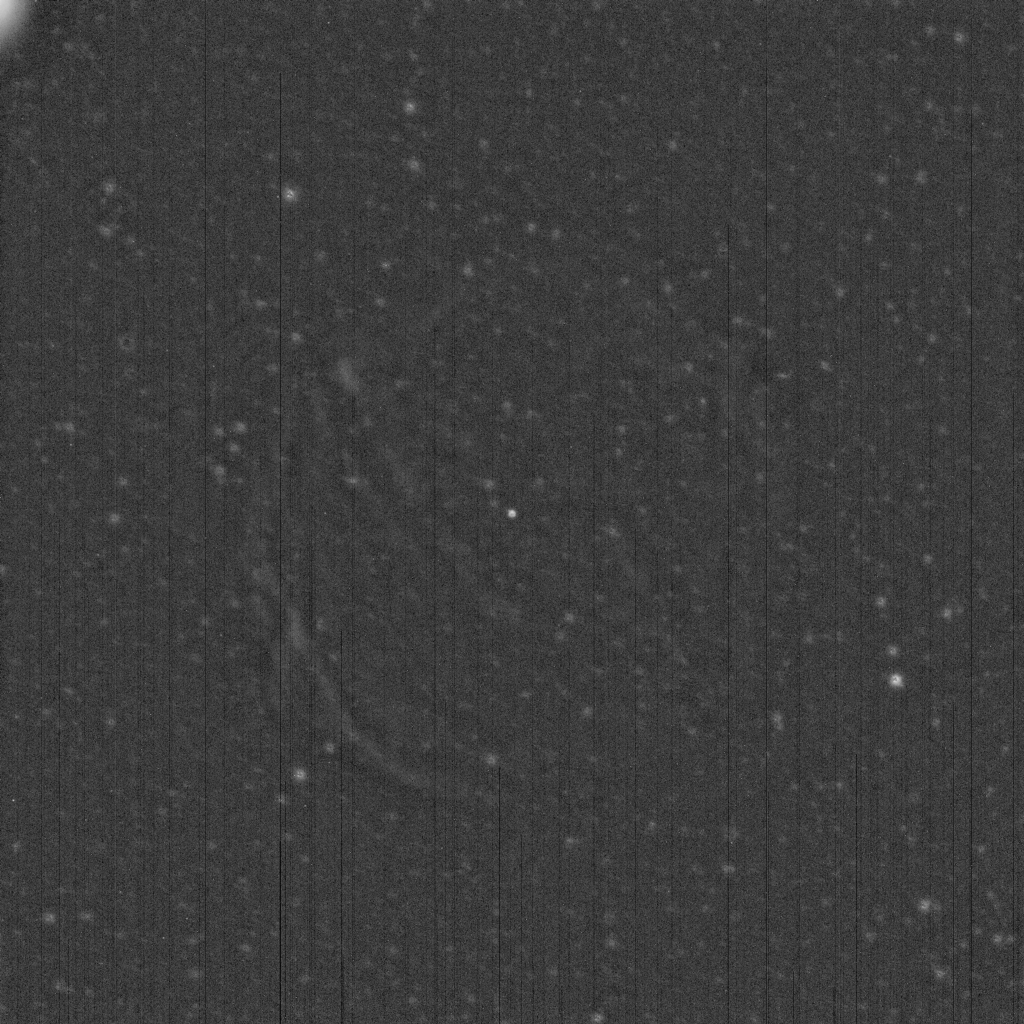
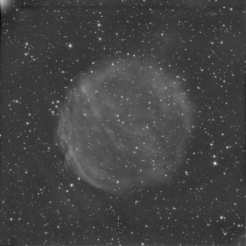
In the following image there is a linear pattern that cannot be completely visible since most of the lines are below the noise floor of the image.
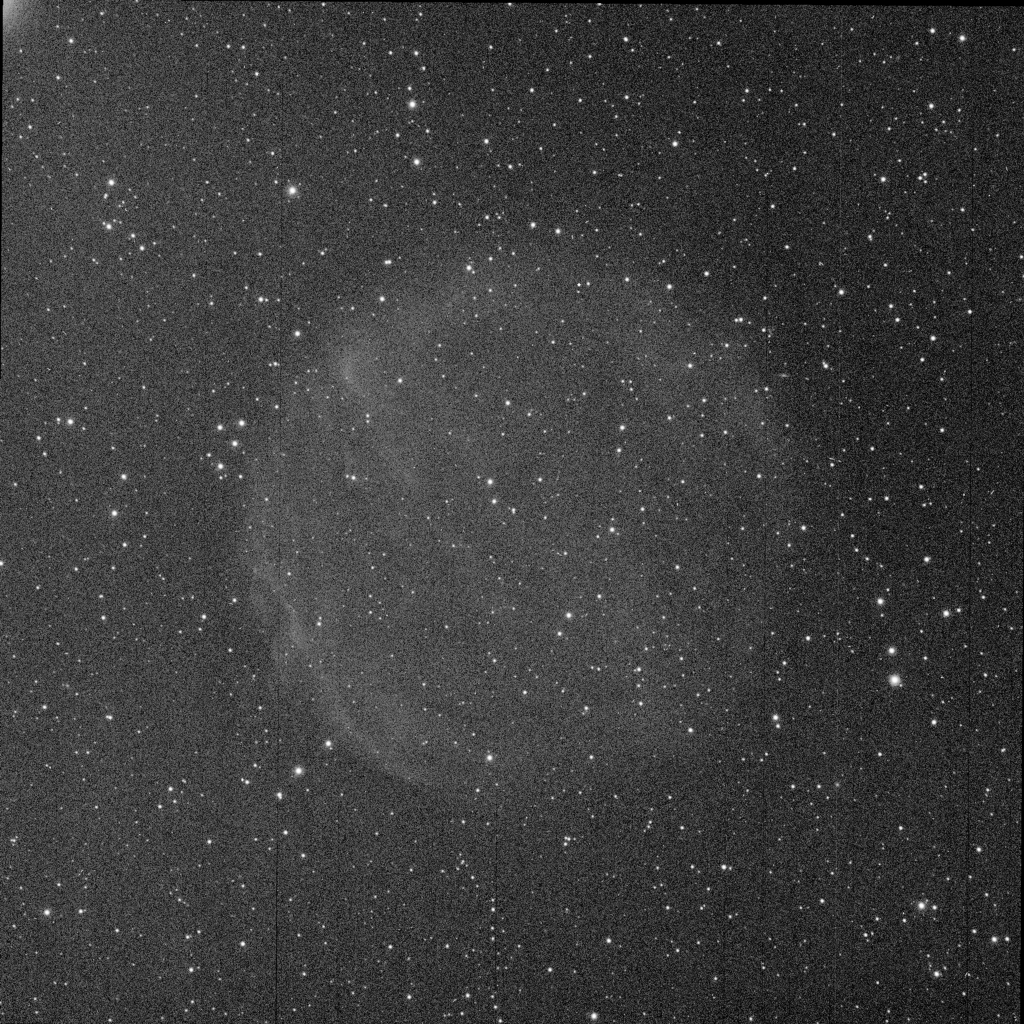
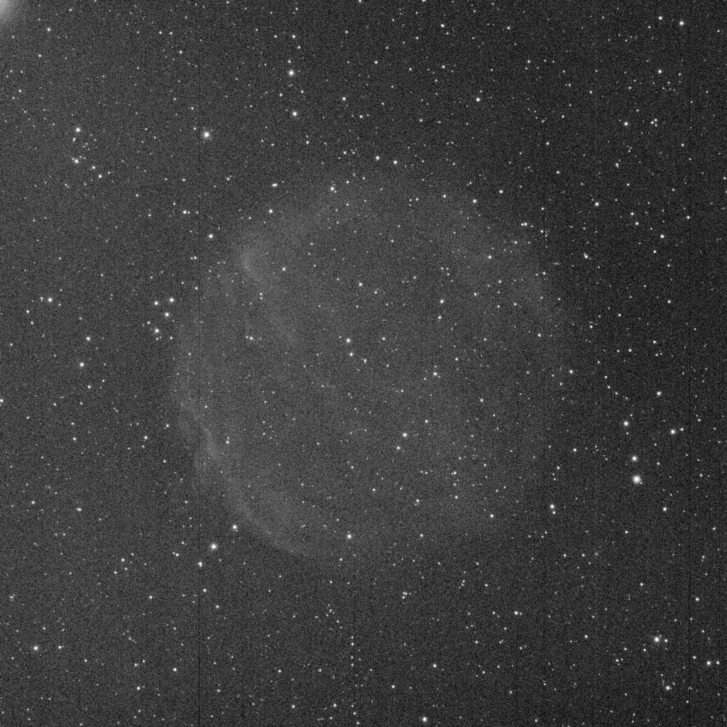
This pattern becomes more visible when we register and integrate all subframes into a master light, because this integrated image has a much higher signal to noise ratio. SNR increases for the objects in the image, but it also increases for the linear pattern since this pattern remains the same througout the subframe set. In the mouse over below you can see how some of the lower contrast line defects emerge in the higher-SNR master light.

Most of these lines cannot be rejected by the image integration process since they are very close or under the noise floor of single subframes. For the same reason, they cannot be properly added to a column defect list in CosmeticCorrection, since they are not easily visible by inspecting a single subframe. The first step in the workflow to properly detect the defective lines is to have a reference image with a noise level as low as possible, in order to detect all of the defective lines that could emerge after composing the master light. To create this reference image, we can simply integrate all subframes prior to registering them into a master image using ImageIntegration.
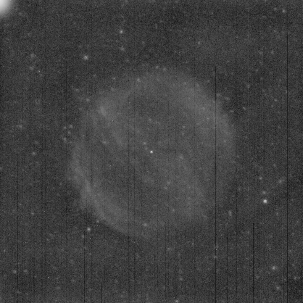
In the image above, we simply add all the subframes from a single filter with the ImageIntegration tool to create the reference image. The visibility of the linear pattern is greatly enhanced in this image, as you can see by comparing it with a single subframe below.

But more important, we are sure that we are looking at the entire line pattern that could be visible in the final integrated master light. We won't have new lines appearing in the master light thanks to the increased signal to noise ratio, since we are using exactly the same image set.
Once we have the reference image, we proceed to detect the line defects. As you can see above, there are entire and partial column defects. The detection of both types of defects is handled by two different routines.
Partial Column Detection
The key to properly detect a partial column defect is to know the Y coordinate of its origin. The algorithm works as follows:
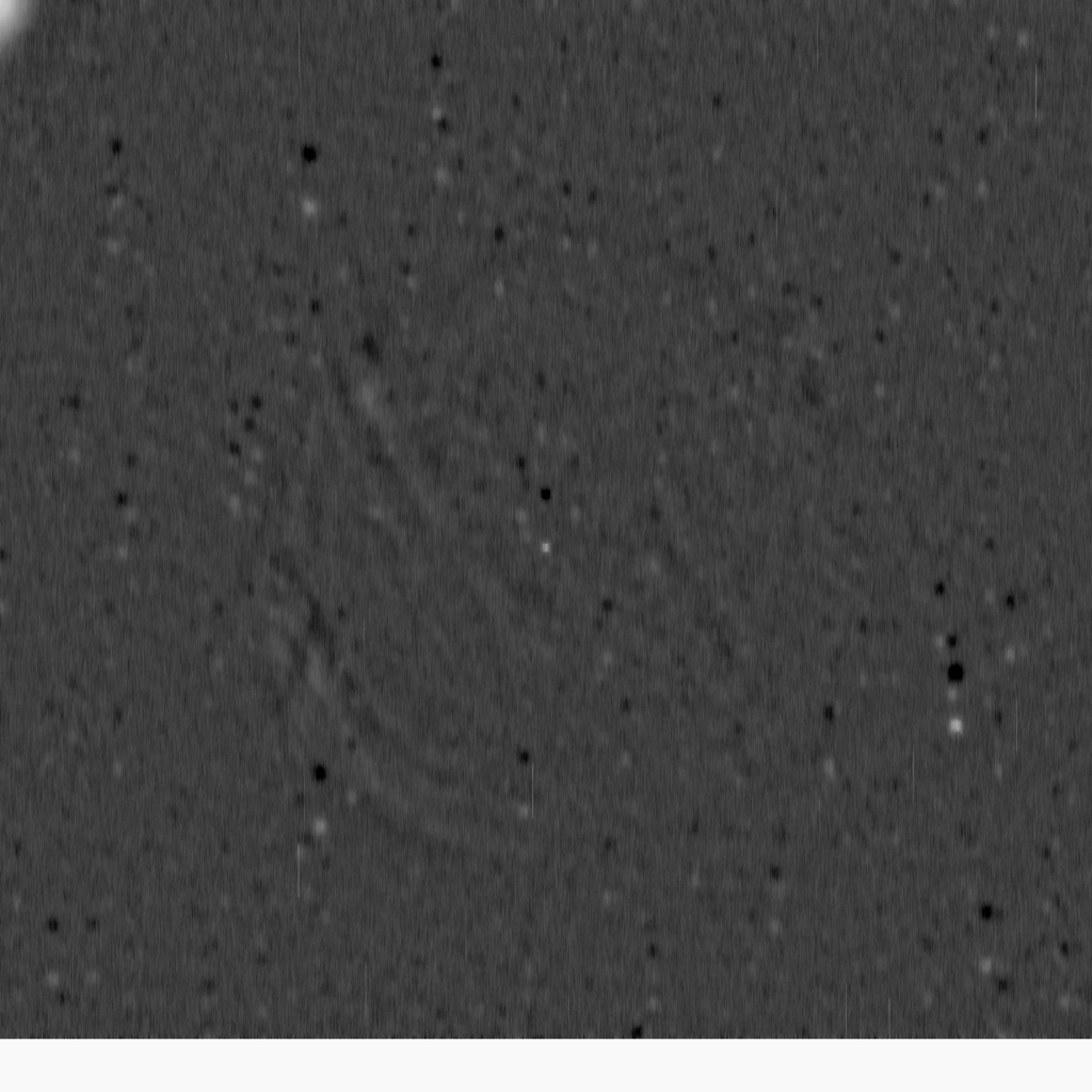
- Step 1. Remove the large structures from the image. This enhances the line structures since they are only one pixel width.
- Step 2. Apply a morphological median filter with a vertical line structuring element. This removes the noise in the vertical direction while keeping the origin of the lines at the same location.

By zooming in the image we can show better the result of the morphological transformation:
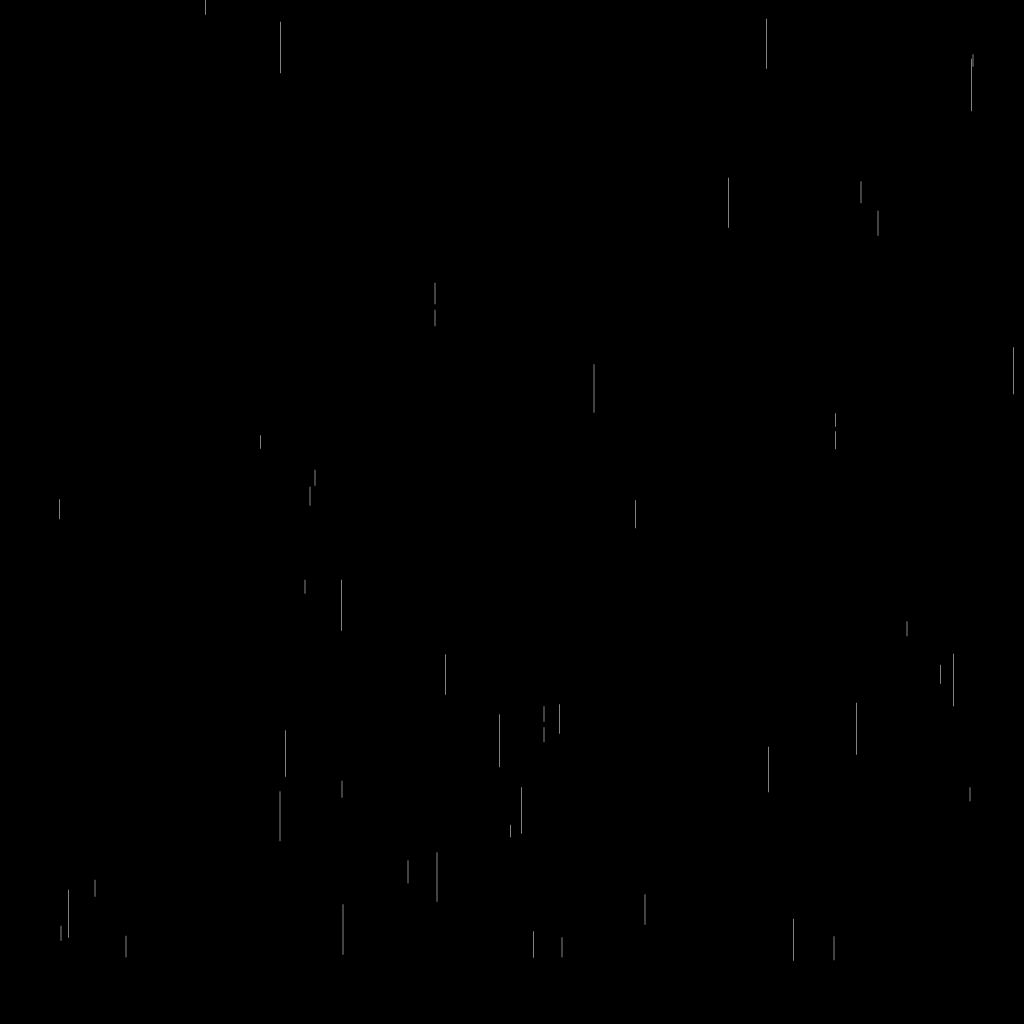
- Step 3. Duplicate the transformed image and shift it vertically.
- Step 4. Subtract the shifted image.
Although there are many surviving structures (mostly coming from star residuals), the subtraction of the shifted image produces bright lines at the beginning of partial lines. A zoomed crop shows it clearly.
- Step 5. Remove again the large-scale structures to further enhance bright line sections.
- Step 6. Binarize the image at a threshold defined by the median pixel value of the image plus a given offset in sigma units.
In the figure below we can see steps 5 and 6, plus the efect of binarizing at 3, 4, 5, 6 and 7 sigmas.
Mouse over:
Shifted image subtracted.
Large scales removed.
Binarized at 3 sigmas.
Binarized at 4 sigmas.
Binarized at 5 sigmas.
Binarized at 6 sigmas.
Binarized at 7 sigmas.
As expected, the higher we set the binarizing threshold the more is decreased the number of detected lines.
- Step 7. Apply a morphological closing operation with the same structuring element to erase short, random surviving lines. The figure below shows the result of this operation after a binarization at 3 sigmas.
Once we have the processed line detection image, we'll only select those lines that have more than half the length of the vertical shift.
Entire Column Detection
The algorithm to detect entire defective columns is simpler because we don't need to detect the origin coordinates of the defect. The algorithm works as follows:
- Step 1. Remove the large structures from the image. This will strengthen line detection.
- Step 2. Calculate the median pixel value of each column. The median is calculated after rejecting bright pixels with a rejection threshold defined in sigma units by the Rejection limit parameter. This will reject all of the stars in the image as well as small, bright diffuse structures. As always, the lower the threshold the more bright pixels will be rejected.
- Step 3. Build a line model image by assigning to each column in the image its calculated median level.
- Step 4. Calculate the median absolute deviation from the median (MAD) of this model image. This value will be used to define a threshold to detect defective columns.
- Step 5. Select the columns having a MAD value higher than the defined threshold.
The figure below shows the steps decribed above and the selected defective columns with thresholds from 3 to 7 sigmas.
Mouse over:
Reference image.
Line model.
Line detection at 3 sigmas.
Line detection at 4 sigmas.
Line detection at 5 sigmas.
Line detection at 6 sigmas.
Line detection at 7 sigmas.
This entire line detection process can be combined with detection of partial columns. Below we show the detection of partial and entire columns with a threshold of 4 sigmas.

The LinearDefectDetection Script
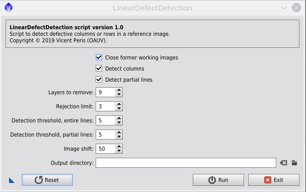
This script is always applied to the active image, so we have to bring the reference image to the top of PixInsight's current workspace. When running the script multiple times on the active image, you can choose to automatically close the working images from the last run by checking the Close former working images check box. Only the target image will remain open in such case.
We can choose to detect defective columns or rows in the image. To detect columns, check the Detect columns check box. By unchecking it the script will detect rows.
We can also choose to detect only entire columns or rows (covering the entire height or width of the image) or, additionally, detect partial column or row defects. The latter detection is activated by checking the Detect partial lines check box. Then you should configure the image shift that will be used to point to the origin of each defect. A value from 50 to 100 pixels usually works well. A too low value will increasingly detect spurious noise structures, but keep in mind that defective lines smaller in length than half the selected shift will never be detected.
The Layers to remove parameter defines the dimensional scale at wich we separate small and large structures, in a dyadic sequence. The default value of 9 means that all structures up to the scale of 29-1 = 256 pixels will be removed from the image, keeping in the resulting small-scale component image all structures with characteristic sizes from 1 to 128 pixels.
The Rejection limit parameter sets the bright pixel rejection threshold, in sigma units, inside each line of the image.
We can separately set the detection threshold for entire and partial lines, in sigma units, with the Entire lines and Partial lines check boxes, respectively. Lower threshold values will always increase the number of detected lines.
In the Output directory field we can choose where to save the defect table.
Script Products
The script generates three new images:
- line_model: — The calculated line pattern present in the reference image. It will contain the entire and partial defective lines, depending on the setup.
- partial_line_detection — If we activate detection of partial lines, the script will output the partial line detection image containing the segments that point to the origin of each partial line defect. Keep in mind that only those lines having a length of more than half the configured shift parameter will be detected as actual defects.
- line_detection: — A representation of dispersion computed for each line in integer sigma units. In this image, the lines with a value at a distance of less than one sigma from the median are displayed as black. Those lines at a distance greater than or equal to the configured detection threshold are displayed as white. The lines at intermediate distances have gray values evenly distributed by integer sigma values. For instance, if the detection threshold is set to 3 sigmas, lines between 1 and 2 sigmas will have a value of 0.333 and lines between 2 and 3 sigmas will have a value of 0.666. All lines at 3 or more sigmas will be white; only these white lines will be detected as defective.
The line detection script also outputs a CosmeticCorrection-compatible plain text file containing the detected defects. Below you can see an example of one of these files:
                  Col 570 1559 2047

                  Col 580 0 2047

                  Col 584 0 2047

                  Col 585 0 2047

                  Col 588 0 2047

                  Col 589 0 2047

                  Col 593 1878 2047

                  Col 614 0 2047

                  Col 619 1050 2047

                  Col 619 0 1049

                  Col 620 2037 2047

                  Col 620 0 2036

                  Col 622 0 2047

                  Col 624 0 2047

                  Col 629 972 2047
This text file can be input in LinearPatternSubtraction to correct the defective columns in each subframe.
Linear Pattern Subtraction
After detecting the defective columns in the reference image, we proceed to correct these defects in each subframe. The defect list produced by LinearDefectDetection can be used with LinearPatternSubtraction to limit the correction process to the desired columns. This script will calculate the median level of each defective column in each subframe using the same methodology as LinearDefectDetection to detect entire lines:
- Step 1. Remove the large-scale structures from the image. This will strengthen line detection.
- Step 2. Calculate the median pixel value of each column. This value is calculated after applying two different pixel rejections. First, we reject all pixels in the unprocessed target image having a value higher than a defined threshold; this will reject bright extended objects such as galaxies or nebulae. The second rejection will reject bright pixels in the image after removing the large-scale structures. This will reject all of the stars and small and bright diffuse structures. As always, the lower the threshold the more bright pixels will be rejected, by both rejections.
- Step 3. Build a line model for each subframe. In this model, each defective column will have its calculated median value, while non-defective pixels will simply have the median value of the entire image.
- Step 4. Subtract the line model from the subframe.
Below you have a single subframe and its line model calculated from the detected defective columns.
Here is a comparison between the original and the corrected subframes:

The LinearPatternSubtraction Script
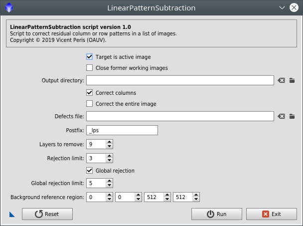
You can choose to apply the script either to the active image, or to a list of images. The latter option is selected by unchecking the Target is active image check box. In such case, an Input files section will appear where you can select the files to be processed. You should then also properly set the Output directory field. As in LinearDefectDetection, you can choose to close the former working images if you're making tests to find optimal parameters on the active image.
This script can also correct defective columns or rows. Check the "Correct columns" check box accordingly, in the same way as in LinearDefectDetection.
You can choose whether to correct all defective columns or rows in your image, or just a set of specific defects. To correct all the image, check the Correct entire image check box. You can additionally specify a defect table file created by CosmeticCorrection or LinearDefectDetection. This is useful when the Correct entire image check box is checked because it lets you specify partial line defects; otherwise, only entire columns or rows will be corrected. If you uncheck the Correct entire image check box, then you should specify a defect table, or otherwise the script will do nothing to the image.
There are three options for the pixel rejection algorithm. Global pixel rejection (based on the target image prior to any processing) is optional. You can choose to apply it with the Global rejection limit check box and then specifying the Global rejection limit parameter in sigma units. Usually this parameter works well having more tolerance than the second rejection, but you should experiment when you have extended nebulae covering a large portion of the image. The Rejection limit parameter defines the number of sigmas to apply a rejection in each line of the image after multiscale processing; remember that this is important to reject any small and bright objects inside the line, like stars.
The Layers to remove parameter defines the scale separation in the same way as the LinearDefectDetection script does.
The last thing to configure in this script is a background reference area. In this area we'll be measuring the noise, and the rejection limits will be based on this measurement. The sky background signal level is also used in some internal processing, so it's important that you always select the darker area of your image here.
Script Products
The script can be applied either to the current active image, or to a list of disk image files. In the latter case, the script will generate corrected image files on the output directory.
If we choose to apply the script to the active image, after correcting the image the script will additionally create the following images:
- LS — The large-scale component. This image has the structures that are subtracted to isolate the small-scale components.
- SS — The small-scale component, containing the linear structures to be modeled. In this image, rejected pixels are set to white.
- Pattern — The calculated line pattern that has been subtracted from the image.
Applying LinearPatternSubtraction to a Master Light Image
Optionally, we can apply LinearPatternSubtraction to a master light image generated by the ImageIntegration tool. In this case, the script can subtract any residual column or row pattern. There are some tips to take into account:
- Open the master light and check the Target is active image check box.
- You cannot specify a defect table file to by applied to a master light because the defects in each subtrame have been displaced by image registration. You should always check the Correct entire image check box and leave empty the Defect table file path field.
- Partial column or row defects cannot be corrected in an integrated image since the origin of each defect has been blurred by image registration. This kind of defects can only be corrected following the methodology described above.
- Keep in mind that this step is always optional and should be used only if necessary. Check your master light for any residual linear pattern, and check that the applied correction does not introduce any artifacts. In some noisy master light images, the script may model a line pattern that comes purely from the image noise, and then you'll be creating lines instead of removing them.
Defective Line Correction in the Preprocessing Workflow
Since this defect correction is done before the image registration process, the steps described above should be included in the preprocessing workflow as follows:
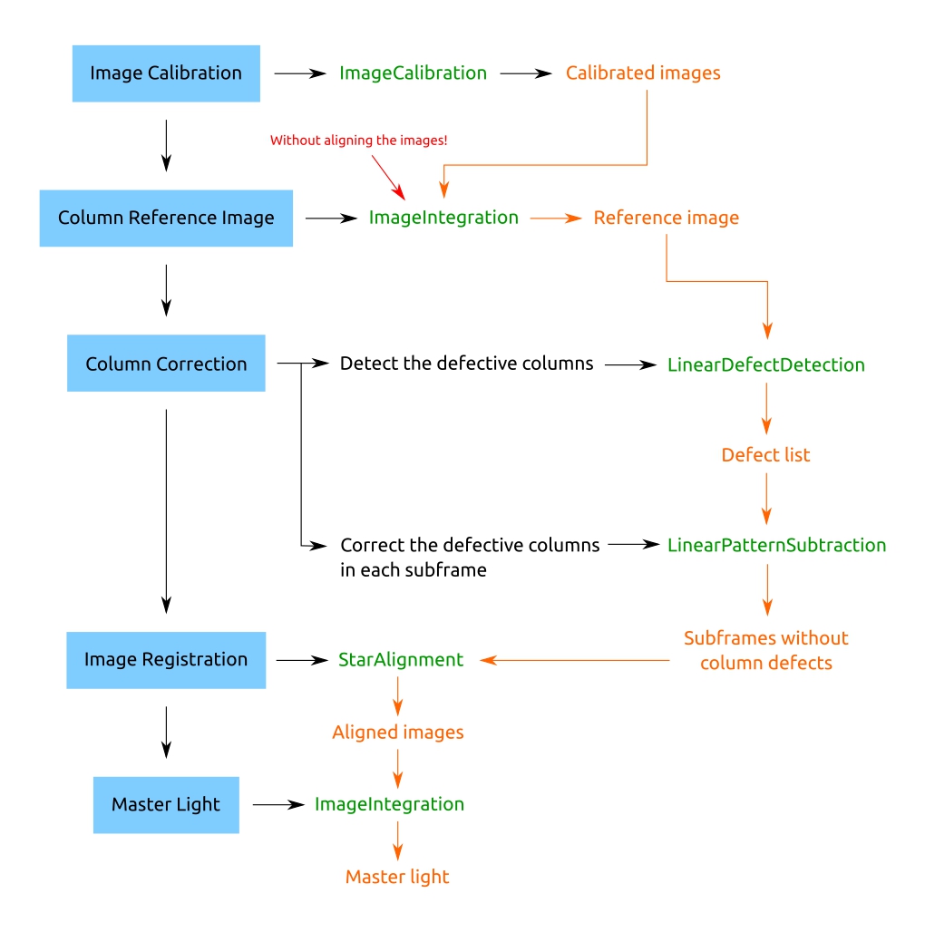
Corrected Master Light
The image below shows the result of the proposed workflow with partial and entire column correction. We can compare it to the result without defect correction:
Disclaimer — The master light above still contains other camera-related patterns that have been not corrected, since they are out of the scope of this article. Therefore, this master light has been generated only for illustrative purpouses and is not representative of the author's photographic work.