
Hi everybody,
Continuing with descriptions of the new module versions that we have released recently, I'll summarize the new features and improvements implemented in the latest version of StarAlignment. I already have described the new ImageIntegration tool in a previous post.
New Star Detector
Many of the most important problems in previous versions of StarAlignment were related to its star detection routine. Star detection is not a trivial task by any means. On one hand, a star detection routine has to be exhaustive: in general, we want to detect as many stars as possible. On the other hand, there are additional requirements that complicate the design and implementation of a good star detection algorithm: it must be scale-invariant (given two images of the same subject at different scales, we want to detect two compatible sets of stars); it must be robust to illumination changes (we need to detect stars on free sky regions and on extended nebular regions); it must be robust to multiple stars and crowded fields, and it must be able to distinguish between true stars and small nonstellar structures such as bright nebular features, hot pixels and cosmic rays. In addition, it should be highly controllable (for example, we need control over detection sensitivity and rejection of elongated stars), computationally efficient, and accurate.
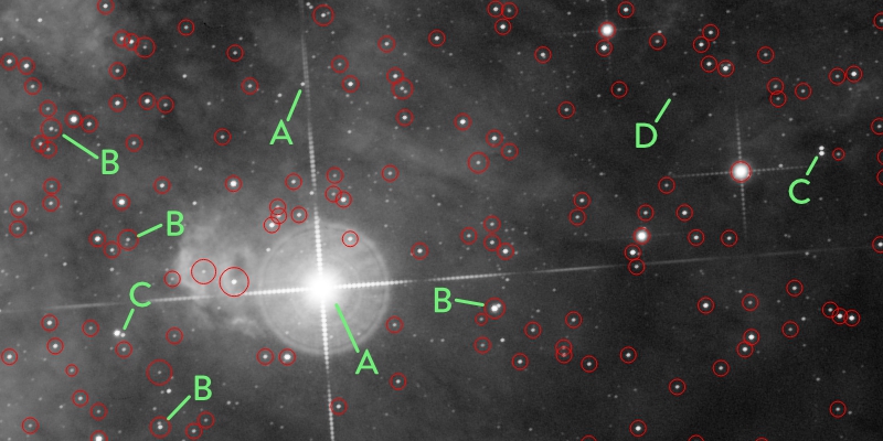
Example of star detection
A - Too complex structure; star parameters uncertain.
B - Crowded, but an accurate position is feasible.
C - Crowded, cannot compute an accurate position.
D - Too dim star (as per current detection sensitivity).
The old star detection routine was based on a multiscale algorithm. This wavelet-based algorithm is very robust to illumination variations and is also very controllable and efficient, but it has a serious drawback: its multiscale nature makes it strongly scale-dependent. For example, the set of detected stars on a relatively small crop of an image were different from the stars detected on the whole image for the same region. In general, star detection on images subject to relatively small scale variations led to incompatible sets. This was causing severe limitations in the capabilities and applicability of the StarAlignment tool.
Most of these limitations are now overcome by the new star detection algorithm. If you are interested in more details about this algorithm, I have released a JavaScript version that you can evaluate in the development forum boards. The new algorithm is robust to strong scale variations, considerably faster than the old algorithm, and more accurate. It is somewhat less controllable, but this doesn't cause practical problems in most cases. For practical use of the StarAlignment tool, you can just ignore the star detection section in virtually all cases, as happened in previous versions. It will just work faster and better.
New Star Matching Descriptors
Previous versions of the StarAlignment tool used triangle similarity[1][2] to find star pair matches between images. Triangle similarity is invariant to some affine transformations: translation, rotation, and uniform scale variation. Clearly, this excludes any form of local distortion, and also excludes more general linear transformations such as projective transformations (homographies). As a result, previous versions of StarAlignment were using a too rigid star matching device, and despite some strategies that I had implemented to palliate this problem (such as favoring generation of small-scale triangles to improve tolerance to large-scale deformations), triangle similarity was limiting the applicability of this tool considerably.
The new version of StarAlignment uses a different geometrical device to find star pair matches: polygonal descriptors.[3][4] Quadrilaterals (aka quads), pentagons, hexagons, heptagons and octagons are supported in the current StarAlignment version. By default, pentagons are used. A pentagon descriptor looks like the following figure.
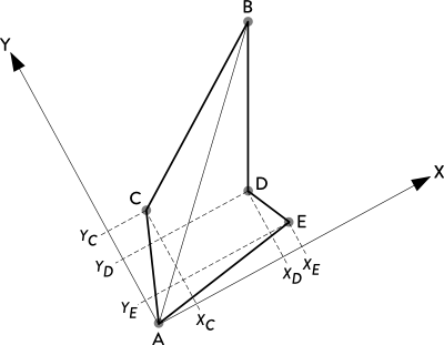
Without entering many details, the two most distant stars of a polygon are used to define a local coordinate system, where the other N?2 stars (N being the number of stars, equal to the number of polygon sides) are identified by their local coordinates to form a hash code of length 2?(N ? 2). With the pentagon descriptor shown above, the local coordinate system would be defined by the pair {A,B}, and the descriptor hash code would be the sequence {XCYCXDYDXEYE} of local coordinates in lexicographical order. Polygonal descriptors are invariant to affine transformations (translation, rotation and scaling), and if properly implemented, they are also quite robust to global projective transformations and local distortions.
Besides invariance and robustness to geometrical transformations, the strength of polygonal descriptors lies in their low uncertainty. A polygon formed with N stars associates N?2 triangles. For example, a quad descriptor is equivalent to two triangles tied together. Hence, in the context of searching for a descriptor among all of the stars in an image (as part of a star matching routine), the uncertainty of a quad is half the uncertainty of a single triangle, the uncertainty of a pentagon is one third, and so on. Less uncertainty leads to less false star pair matches, so the initial set of putative star pair matches contains a smaller proportion of outliers, and the overall image registration process is considerably more robust and efficient even under difficult conditions.
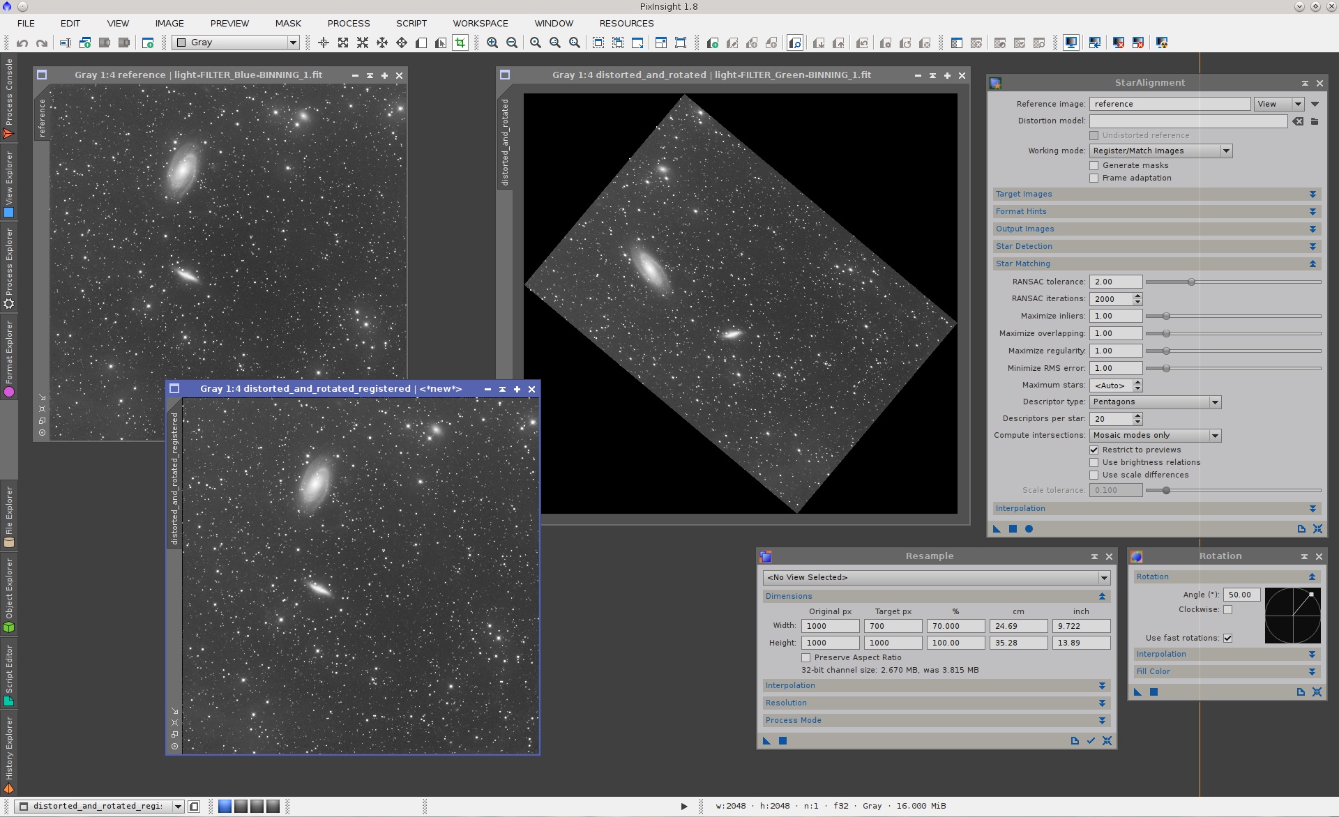
Let's put a few examples to demonstrate the improved performance of the new StarAlignment version. I'll start with a moderately nontrivial problem: nonuniform scaling.

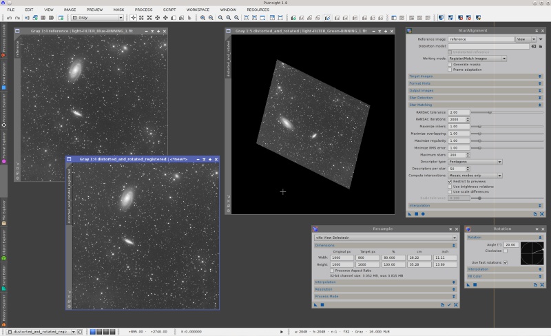
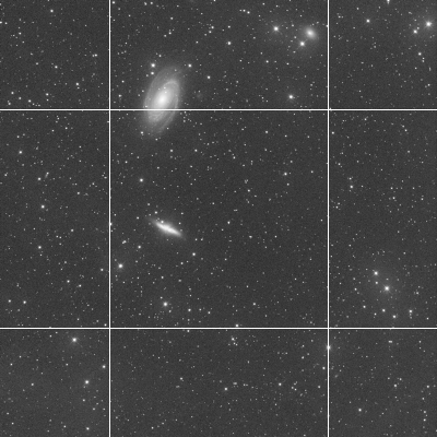
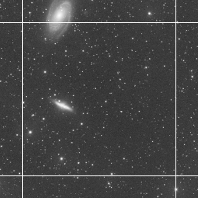
On the screenshot above, we have two master light frames acquired with blue and green filters, respectively. It is important to point out that they are two different images, not a duplicated image. The images are linear and have automatic screen stretch functions applied. The green frame, namely the distorted_and_rotated view, has been transformed as follows:
- Resample: horizontal scaling factor = 70%, vertical scaling factor = 100% (preserve aspect ratio disabled).
- Rotation: 50 degrees counter-clockwise.
StarAlignment has registered these images perfectly with default parameters after three automatic tries. This was very difficult or impossible with the old StarAlignment tool.
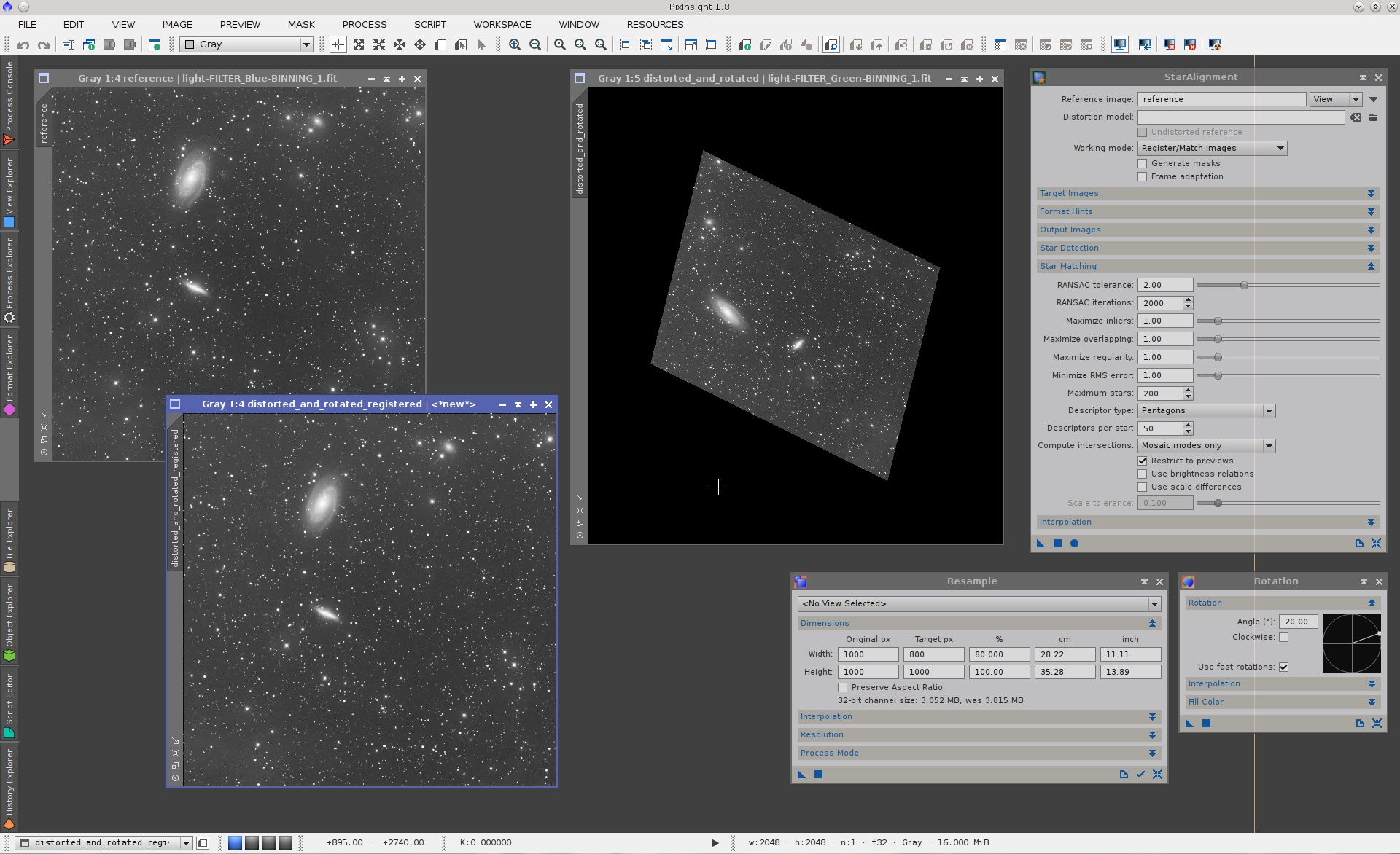
Let's make things slightly more difficult: two consecutive distortion-rotation steps to turn the image into a trapezoid:
The sequence of operations is:
- Resample: horizontal scaling factor = 80%, vertical scaling factor = 100% (preserve aspect ratio disabled).
- Rotation: 50 degrees counter-clockwise.
- Resample: horizontal scaling factor = 80%, vertical scaling factor = 100% (preserve aspect ratio disabled).
- Rotation: 20 degrees counter-clockwise.
In this case I have just increased the number of descriptors per star from its default value of 20 to 50. Then the image has been registered without problems.
Note that the above examples are extreme cases: By default, StarAlignment has not been designed to solve this kind of problems. Yet it can deal with them easily using default or nearly default parameters, thanks to a complete rewrite of the whole star matching routine.
But we can now do much better than this, with the new local distortion correction feature.
Local Distortion
Complex affine transformations that were problematic or even impossible with previous versions of StarAlignment are now handled without any problems. For example, how about travelling on the USS Enterprise for a while? Take a look at our warp core (Galaxy class):
Our warp factors are expressed in pixels. Since this script only transforms the first channel of the active image, its effect is clear when we apply it to a color image (with a warp factor of 150 pixels for better visualization):
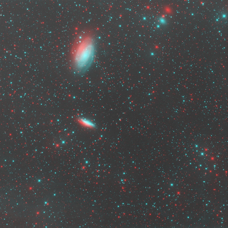
For positive warp factors, this transformation is a linearly increasing radial upscaling, from the center of the image (where the scaling factor is one) to the corners, where the deformation is equal to the warp factor. If you don't believe that this is an affine transformation, look at the following images (original and warped):
The transformation is affine because it preserves parallelism of straight lines. Technically this is known as a central dilation. The new version of PixInsight can register images transformed this way without problems, and of course it can register them with both triangle similarity and polygonal descriptors.
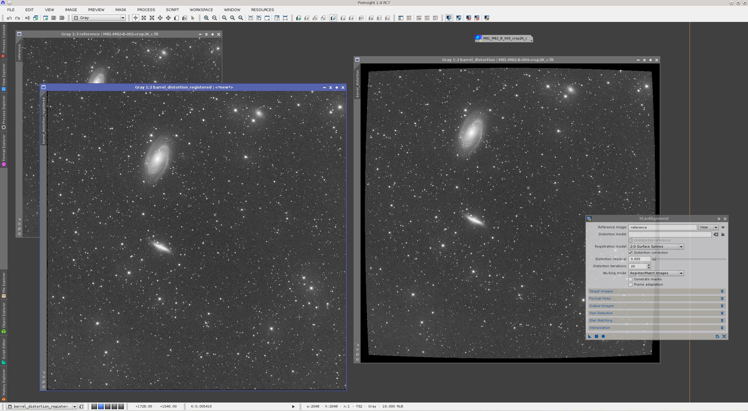
So far this may not seem very impressive, since this type of warping is just an affine transformation, after all. So let's try with nonlinear distortions to really put the tool into test. The following script performs a simulation of second order and fourth order optical distortions, also known as barrel, pincushion, mustache, etc.
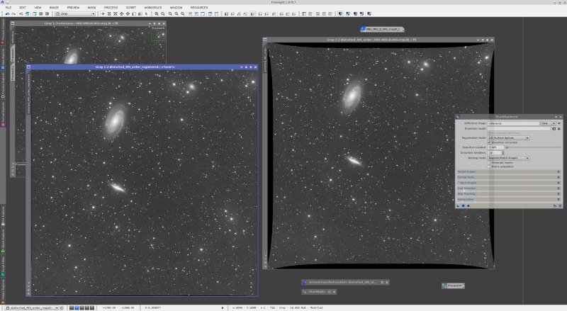
This script implements (partially) Brown's classical distortion model.[5] The K1 and K2 function arguments are the second and fourth order distortion factors, respectively. If we apply the above script to the same M81/M82 image as before, we cause a rather strong barrel distortion. The new version of StarAlignment can register the distorted image easily, thanks to its new arbitrary distortion model feature. You can see the applied parameters on the following screenshot.
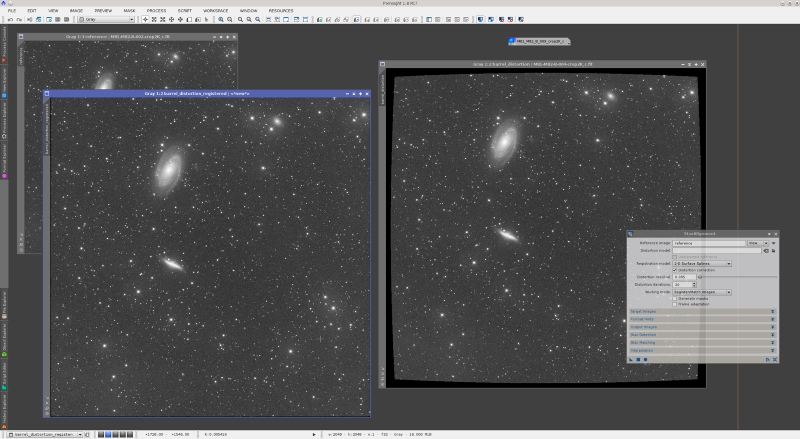
All parameters are by default except distortion correction, which has been enabled, and registration model, which has been set to "2-D surface splines". A surface spline, also known as thin plate, is an extremely flexible interpolation device that can be used to model nonlinear transformations. Thin plates are also necessary to correct for differential distortion, which is the kind of deformations that must be corrected to build accurate wide-field mosaics.
To evaluate the accuracy of StarAlignment with distortion correction, here is an animation of a small crop on the bottom left corner of the image, enlarged 3:1 (sorry for the animated gif image, but there are "web browsers" out there that don't support anything else):
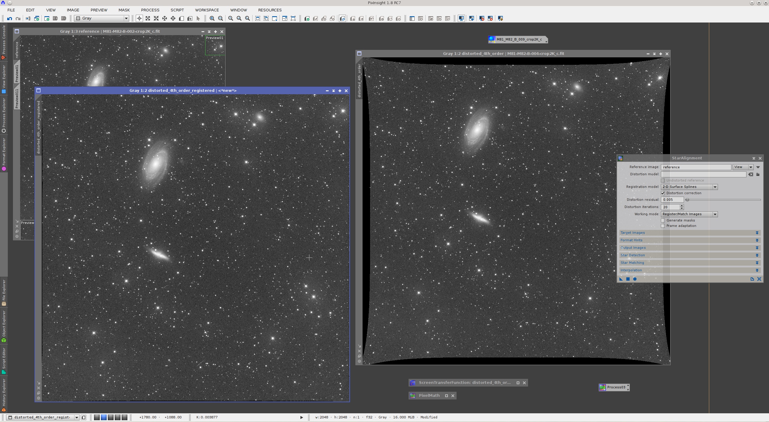
Let's put a more difficult example: fourth order distortions. If we change the parameters of the distortion function in the above script to K1=1?10?7 and K2=?5?10?14, we get the following mix of pincushion and mustache distortion:
Again, StarAlignment can deal with this complex distortion without problems:
Of course, the new distortion correction feature has limitations. On the animation above, note that the stars at the very corners of the registered image are still displaced with respect to the reference image. Other that these four small regions, subpixel registration accuracy is constant for the whole image. A better result could be achieved by tweaking star matching parameters.
The new distortion correction capabilities of StarAlignment allow for accurate registration of images from different telescopes, something that was problematic with previous versions. In many cases, accurate registration of dissimilar images is achievable even without enabling the distortion correction feature, thanks to the flexibility of polygonal descriptors.
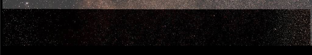
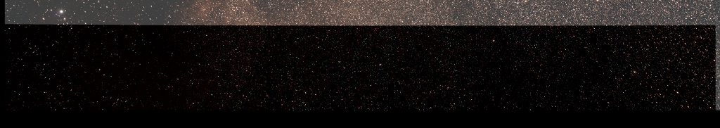
Mosaic construction also benefits greatly from distortion correction. The following screenshot shows an absolutely wonderful mosaic by Thomas W. Earle, which you can see finished on a Gallery forum board post.
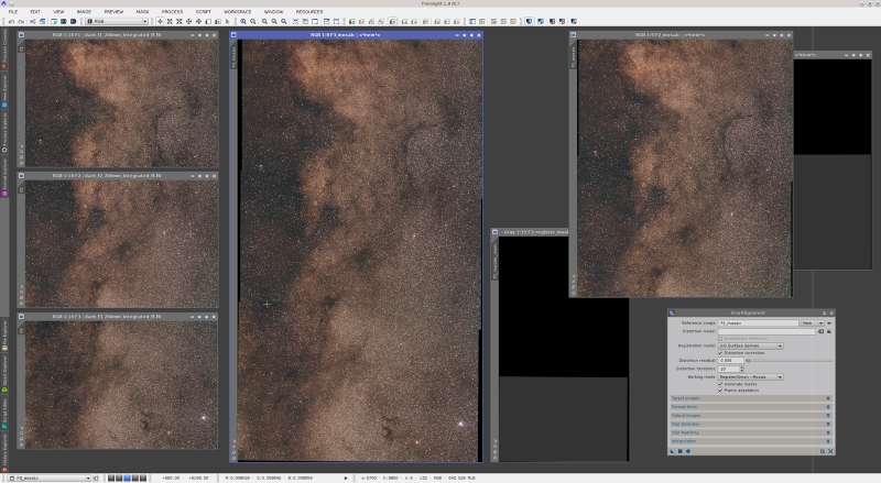
This is a three-panel mosaic of the Milky Way in Aquila, acquired with a Canon EF 200 mm f/2 lens, stopped down to f/4. Wide-field mosaics are difficult due to differential distortions. Basically, the problem is that we are mixing images on areas where they are distorted differently, often with opposite sign curvatures. Previous versions of the StarAlignment tool did a good job thanks to the application of thin plates and small-scale triangle generation, but there were considerable room for improvement. The current version provides a significant improvement.
The following crops are the result of subtracting the registered second (middle) mosaic panel from the reference first (top) panel. The differences in the residuals clearly show the accuracy and correctness of the image registration task.
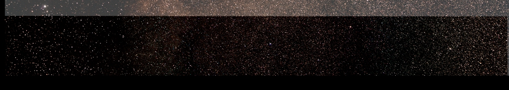
The following animation shows the same registration residuals on a crop of the mosaic seam area, at the original resolution of the image.
On this animation, one can see that the residuals after registration with local distortion correction are mostly due to differences in lateral chromatic aberration. We know this because each residual consists of two lobes, one red and the other green-bluish. Between these lobes there is the star's brightness peak, which has been removed after subtracting the registered images, denoting an accurate registration. After registration without local distortion correction, the residuals clearly show alignment errors.
The local distortion correction routine implements a successive approximations scheme. The whole algorithm is rather complex, but it basically works as follows. The first iteration generates an initial, purely linear (projective) registration model with the initial set of detected stars. At each subsequent iteration, the current registration model is applied (using thin plates) to all detected stars, and a new set of putative star pair matches is generated. To this set a RANSAC (RANdom SAmple Consensus) routine[6] is applied successively with increasing tolerances, trying to find a new model able to match more stars than the preceding one. Each iteration step of this algorithm works as a predictor-corrector step: the current model predicts a set of putative star pair matches, which RANSAC validates and corrects to fit a homographic projection. The concept is similar to predictor-corrector numerical integration algorithms widely used for solar system ephemeris calculation.
At each iteration, the new registration model is more flexible and tends to match more star pairs. The algorithm converges to a solution where the model predicts star positions than can no longer be corrected to match the reference image. An ideal registration model would predict star positions that match perfectly their reference image counterparts. If this happens, the RANSAC correction to the set of predicted star positions is the unit matrix:
So we stop the local distortion correction algorithm when we achieve a correction model very similar to the unit matrix. The stop criterion is:

where H is the corrector transformation matrix, T > 0 is the distortion residual parameter, and ||?|| is the matrix modulus operator (the sum of the absolute values of all matrix elements).
Distortion Models
In addition to the local distortion correction feature, the new version of StarAlignment supports externally defined distortion models. A distortion model can be used to pre-correct the images for optical aberrations such as field curvature, lateral chromatic aberration and other arbitrary geometrical transformations. This way the image registration process can work with undistorted images.
StarAlignment distortion models must be plain text files in standard CSV (Comma-Separated Value) format. Formally, the first line of a valid distortion model can be described as:
The rest of lines define distortion nodes. A distortion node has the form:
where <x>,<y> are the image coordinates of the point of application of a distortion vector, and <dx>,<dy> define the vector's magnitude and direction. The four node elements are floating point numbers expressed in pixels. A valid distortion model has three or more nodes.
In this initial release only thin plate distortion models are supported, so 2DSurfaceSpline and ThinPlate are synonyms. The model order parameter refers to the derivative order of continuity. Second-order models are usually more than sufficient to represent even wildly nonlinear transformations, so they are recommended by default. Third-order models can represent very strong small-scale distortions. Higher order models can easily become unstable and are thus discouraged.
Let's put an example where a distortion model is necessary for successful image registration. The following script applies a cylinder deformation:
The script applies the geometrical transformation and generates the corresponding distortion model in CSV format, suitable to be used with StarAlignment.
When a strong deformation factor is applied, the cylinder transformation poses a very difficult problem for image registration. The next screenshot is an example.
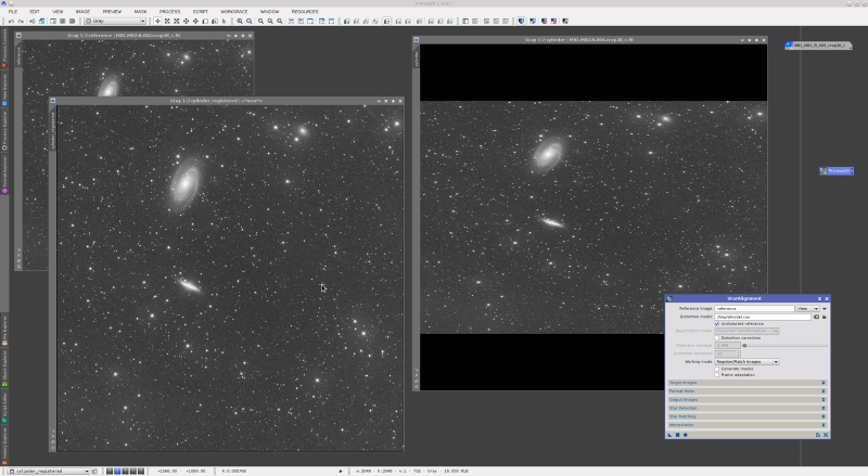
In this case, the undistorted model parameter has been enabled because the registration reference image has no distortion. With the help of a model, StarAlignment registers this image immediately. However, without a distortion model, the image shown in the screenshot above cannot be registered, even with local distortion corrections.
References
[1] Francisco G. Vald?s et al. (1995), FOCAS Automatic Catalog Matching Algorithms, Publications of the Astronomical Society of the Pacific, 107, pp. 1119?1128.
[2] M. Marszalek, P. Rokita (2004), Pattern Matching with Differential Voting and Median Transformation Derivation, Computer Vision and Graphics (Computational Imaging and Vision Series), 32, pp. 1002?1007.
[3] D. Lang, D. W. Hogg, K. Mierle, M. Blanton, and S. Roweis (2010), Astrometry.net: Blind astrometric calibration of arbitrary astronomical images, The Astronomical Journal (AJ), vol. 37, pp. 1782?2800.
[4] G.D. Evangelidis, C. Bauckhage (2011), Efficient and Robust Alignment of Unsynchronized Video Sequences, German Association for Pattern Recognition (DAGM) 2011, Frankfurt.
[5] Brown, D. C. (1966), Decentering Distortion of Lenses, Photogrammetric Engineering, vol. 32, No. 3, pp. 444?462.
[6] Martin A. Fischler, Robert C. Bolles (1981), Random Sample Consensus: A Paradigm for Model Fitting with Applications to Image Analysis and Automated Cartography, Communications of the ACM, Vol. 24 No. 6, pp. 381?395
Continuing with descriptions of the new module versions that we have released recently, I'll summarize the new features and improvements implemented in the latest version of StarAlignment. I already have described the new ImageIntegration tool in a previous post.
New Star Detector
Many of the most important problems in previous versions of StarAlignment were related to its star detection routine. Star detection is not a trivial task by any means. On one hand, a star detection routine has to be exhaustive: in general, we want to detect as many stars as possible. On the other hand, there are additional requirements that complicate the design and implementation of a good star detection algorithm: it must be scale-invariant (given two images of the same subject at different scales, we want to detect two compatible sets of stars); it must be robust to illumination changes (we need to detect stars on free sky regions and on extended nebular regions); it must be robust to multiple stars and crowded fields, and it must be able to distinguish between true stars and small nonstellar structures such as bright nebular features, hot pixels and cosmic rays. In addition, it should be highly controllable (for example, we need control over detection sensitivity and rejection of elongated stars), computationally efficient, and accurate.
Example of star detection
A - Too complex structure; star parameters uncertain.
B - Crowded, but an accurate position is feasible.
C - Crowded, cannot compute an accurate position.
D - Too dim star (as per current detection sensitivity).
The old star detection routine was based on a multiscale algorithm. This wavelet-based algorithm is very robust to illumination variations and is also very controllable and efficient, but it has a serious drawback: its multiscale nature makes it strongly scale-dependent. For example, the set of detected stars on a relatively small crop of an image were different from the stars detected on the whole image for the same region. In general, star detection on images subject to relatively small scale variations led to incompatible sets. This was causing severe limitations in the capabilities and applicability of the StarAlignment tool.
Most of these limitations are now overcome by the new star detection algorithm. If you are interested in more details about this algorithm, I have released a JavaScript version that you can evaluate in the development forum boards. The new algorithm is robust to strong scale variations, considerably faster than the old algorithm, and more accurate. It is somewhat less controllable, but this doesn't cause practical problems in most cases. For practical use of the StarAlignment tool, you can just ignore the star detection section in virtually all cases, as happened in previous versions. It will just work faster and better.
New Star Matching Descriptors
Previous versions of the StarAlignment tool used triangle similarity[1][2] to find star pair matches between images. Triangle similarity is invariant to some affine transformations: translation, rotation, and uniform scale variation. Clearly, this excludes any form of local distortion, and also excludes more general linear transformations such as projective transformations (homographies). As a result, previous versions of StarAlignment were using a too rigid star matching device, and despite some strategies that I had implemented to palliate this problem (such as favoring generation of small-scale triangles to improve tolerance to large-scale deformations), triangle similarity was limiting the applicability of this tool considerably.
The new version of StarAlignment uses a different geometrical device to find star pair matches: polygonal descriptors.[3][4] Quadrilaterals (aka quads), pentagons, hexagons, heptagons and octagons are supported in the current StarAlignment version. By default, pentagons are used. A pentagon descriptor looks like the following figure.
Without entering many details, the two most distant stars of a polygon are used to define a local coordinate system, where the other N?2 stars (N being the number of stars, equal to the number of polygon sides) are identified by their local coordinates to form a hash code of length 2?(N ? 2). With the pentagon descriptor shown above, the local coordinate system would be defined by the pair {A,B}, and the descriptor hash code would be the sequence {XCYCXDYDXEYE} of local coordinates in lexicographical order. Polygonal descriptors are invariant to affine transformations (translation, rotation and scaling), and if properly implemented, they are also quite robust to global projective transformations and local distortions.
Besides invariance and robustness to geometrical transformations, the strength of polygonal descriptors lies in their low uncertainty. A polygon formed with N stars associates N?2 triangles. For example, a quad descriptor is equivalent to two triangles tied together. Hence, in the context of searching for a descriptor among all of the stars in an image (as part of a star matching routine), the uncertainty of a quad is half the uncertainty of a single triangle, the uncertainty of a pentagon is one third, and so on. Less uncertainty leads to less false star pair matches, so the initial set of putative star pair matches contains a smaller proportion of outliers, and the overall image registration process is considerably more robust and efficient even under difficult conditions.
Let's put a few examples to demonstrate the improved performance of the new StarAlignment version. I'll start with a moderately nontrivial problem: nonuniform scaling.
On the screenshot above, we have two master light frames acquired with blue and green filters, respectively. It is important to point out that they are two different images, not a duplicated image. The images are linear and have automatic screen stretch functions applied. The green frame, namely the distorted_and_rotated view, has been transformed as follows:
- Resample: horizontal scaling factor = 70%, vertical scaling factor = 100% (preserve aspect ratio disabled).
- Rotation: 50 degrees counter-clockwise.
StarAlignment has registered these images perfectly with default parameters after three automatic tries. This was very difficult or impossible with the old StarAlignment tool.
Let's make things slightly more difficult: two consecutive distortion-rotation steps to turn the image into a trapezoid:
The sequence of operations is:
- Resample: horizontal scaling factor = 80%, vertical scaling factor = 100% (preserve aspect ratio disabled).
- Rotation: 50 degrees counter-clockwise.
- Resample: horizontal scaling factor = 80%, vertical scaling factor = 100% (preserve aspect ratio disabled).
- Rotation: 20 degrees counter-clockwise.
In this case I have just increased the number of descriptors per star from its default value of 20 to 50. Then the image has been registered without problems.
Note that the above examples are extreme cases: By default, StarAlignment has not been designed to solve this kind of problems. Yet it can deal with them easily using default or nearly default parameters, thanks to a complete rewrite of the whole star matching routine.
But we can now do much better than this, with the new local distortion correction feature.
Local Distortion
Complex affine transformations that were problematic or even impossible with previous versions of StarAlignment are now handled without any problems. For example, how about travelling on the USS Enterprise for a while? Take a look at our warp core (Galaxy class):
Code:
function affineWarp( image, warpFactor )
{
   var c = image.bounds.center;
   var r = c.distanceTo( 0, 0 );
   var w = image.width;
   var h = image.height;

   var work = new Image( image );

   for ( var y = 0; y < h; ++y )
      for ( var x = 0; x < w; ++x )
      {
         var dx = x - c.x;
         var dy = y - c.y;
         var dr = Math.sqrt( dx*dx + dy*dy );
         var fr = warpFactor*dr/r;
         var fa = Math.atan2( dy, dx );
         var fx = fr*Math.cos( fa );
         var fy = fr*Math.sin( fa );
         image.setSample( work.interpolate( x-fx, y-fy ), x, y );
      }
}

var window = ImageWindow.activeWindow;
var view = window.mainView;
view.beginProcess();
affineWarp( view.image, 300 );
view.endProcess();
Our warp factors are expressed in pixels. Since this script only transforms the first channel of the active image, its effect is clear when we apply it to a color image (with a warp factor of 150 pixels for better visualization):
For positive warp factors, this transformation is a linearly increasing radial upscaling, from the center of the image (where the scaling factor is one) to the corners, where the deformation is equal to the warp factor. If you don't believe that this is an affine transformation, look at the following images (original and warped):
The transformation is affine because it preserves parallelism of straight lines. Technically this is known as a central dilation. The new version of PixInsight can register images transformed this way without problems, and of course it can register them with both triangle similarity and polygonal descriptors.
So far this may not seem very impressive, since this type of warping is just an affine transformation, after all. So let's try with nonlinear distortions to really put the tool into test. The following script performs a simulation of second order and fourth order optical distortions, also known as barrel, pincushion, mustache, etc.
Code:
function distortion( image, K1, K2 )
{
   if ( typeof( K1 ) == "undefined" )
      K1 = 0;
   if ( typeof( K2 ) == "undefined" )
      K2 = 0;

   var c = image.bounds.center;
   var w = image.width;
   var h = image.height;

   var work = new Image( image );

   for ( var y = 0; y < h; ++y )
      for ( var x = 0; x < w; ++x )
      {
         var dx = x - c.x;
         var dy = y - c.y;
         var r = Math.sqrt( dx*dx + dy*dy );
         var r2 = r*r;
         var k = K1*r2 + K2*r2*r2;
         var xu = x + dx*k;
         var yu = y + dy*k;
         image.setSample( work.bounds.includes( xu, yu ) ? work.interpolate( xu, yu ) : 0, x, y );
      }
}

var window = ImageWindow.activeWindow;
var view = window.mainView;
// Barrel distortion
view.beginProcess();
distortion( view.image, 5.0e-08 );
view.endProcess();
This script implements (partially) Brown's classical distortion model.[5] The K1 and K2 function arguments are the second and fourth order distortion factors, respectively. If we apply the above script to the same M81/M82 image as before, we cause a rather strong barrel distortion. The new version of StarAlignment can register the distorted image easily, thanks to its new arbitrary distortion model feature. You can see the applied parameters on the following screenshot.
All parameters are by default except distortion correction, which has been enabled, and registration model, which has been set to "2-D surface splines". A surface spline, also known as thin plate, is an extremely flexible interpolation device that can be used to model nonlinear transformations. Thin plates are also necessary to correct for differential distortion, which is the kind of deformations that must be corrected to build accurate wide-field mosaics.
To evaluate the accuracy of StarAlignment with distortion correction, here is an animation of a small crop on the bottom left corner of the image, enlarged 3:1 (sorry for the animated gif image, but there are "web browsers" out there that don't support anything else):
Let's put a more difficult example: fourth order distortions. If we change the parameters of the distortion function in the above script to K1=1?10?7 and K2=?5?10?14, we get the following mix of pincushion and mustache distortion:
Again, StarAlignment can deal with this complex distortion without problems:
Of course, the new distortion correction feature has limitations. On the animation above, note that the stars at the very corners of the registered image are still displaced with respect to the reference image. Other that these four small regions, subpixel registration accuracy is constant for the whole image. A better result could be achieved by tweaking star matching parameters.
The new distortion correction capabilities of StarAlignment allow for accurate registration of images from different telescopes, something that was problematic with previous versions. In many cases, accurate registration of dissimilar images is achievable even without enabling the distortion correction feature, thanks to the flexibility of polygonal descriptors.
Mosaic construction also benefits greatly from distortion correction. The following screenshot shows an absolutely wonderful mosaic by Thomas W. Earle, which you can see finished on a Gallery forum board post.

This is a three-panel mosaic of the Milky Way in Aquila, acquired with a Canon EF 200 mm f/2 lens, stopped down to f/4. Wide-field mosaics are difficult due to differential distortions. Basically, the problem is that we are mixing images on areas where they are distorted differently, often with opposite sign curvatures. Previous versions of the StarAlignment tool did a good job thanks to the application of thin plates and small-scale triangle generation, but there were considerable room for improvement. The current version provides a significant improvement.
The following crops are the result of subtracting the registered second (middle) mosaic panel from the reference first (top) panel. The differences in the residuals clearly show the accuracy and correctness of the image registration task.
Registration residuals, projective registration model, no local distortion correction.
Registration residuals, thin plates registration model, no local distortion correction.
Registration residuals, thin plates registration model with local distortion correction.
The following animation shows the same registration residuals on a crop of the mosaic seam area, at the original resolution of the image.
Mosaic registration residuals
On this animation, one can see that the residuals after registration with local distortion correction are mostly due to differences in lateral chromatic aberration. We know this because each residual consists of two lobes, one red and the other green-bluish. Between these lobes there is the star's brightness peak, which has been removed after subtracting the registered images, denoting an accurate registration. After registration without local distortion correction, the residuals clearly show alignment errors.
The local distortion correction routine implements a successive approximations scheme. The whole algorithm is rather complex, but it basically works as follows. The first iteration generates an initial, purely linear (projective) registration model with the initial set of detected stars. At each subsequent iteration, the current registration model is applied (using thin plates) to all detected stars, and a new set of putative star pair matches is generated. To this set a RANSAC (RANdom SAmple Consensus) routine[6] is applied successively with increasing tolerances, trying to find a new model able to match more stars than the preceding one. Each iteration step of this algorithm works as a predictor-corrector step: the current model predicts a set of putative star pair matches, which RANSAC validates and corrects to fit a homographic projection. The concept is similar to predictor-corrector numerical integration algorithms widely used for solar system ephemeris calculation.
At each iteration, the new registration model is more flexible and tends to match more star pairs. The algorithm converges to a solution where the model predicts star positions than can no longer be corrected to match the reference image. An ideal registration model would predict star positions that match perfectly their reference image counterparts. If this happens, the RANSAC correction to the set of predicted star positions is the unit matrix:
Code:
1 0 0
Code:
0 1 0
Code:
0 0 1So we stop the local distortion correction algorithm when we achieve a correction model very similar to the unit matrix. The stop criterion is:
where H is the corrector transformation matrix, T > 0 is the distortion residual parameter, and ||?|| is the matrix modulus operator (the sum of the absolute values of all matrix elements).
Distortion Models
In addition to the local distortion correction feature, the new version of StarAlignment supports externally defined distortion models. A distortion model can be used to pre-correct the images for optical aberrations such as field curvature, lateral chromatic aberration and other arbitrary geometrical transformations. This way the image registration process can work with undistorted images.
StarAlignment distortion models must be plain text files in standard CSV (Comma-Separated Value) format. Formally, the first line of a valid distortion model can be described as:
Code:
<model-device>, <model-order>

<model-device>: one of:
   2DSurfaceSpline
   ThinPlate

<model-order>: one of:
   2
   3
   4
   5
The rest of lines define distortion nodes. A distortion node has the form:
Code:
<x>, <y>, <dx>, <dy>where <x>,<y> are the image coordinates of the point of application of a distortion vector, and <dx>,<dy> define the vector's magnitude and direction. The four node elements are floating point numbers expressed in pixels. A valid distortion model has three or more nodes.
In this initial release only thin plate distortion models are supported, so 2DSurfaceSpline and ThinPlate are synonyms. The model order parameter refers to the derivative order of continuity. Second-order models are usually more than sufficient to represent even wildly nonlinear transformations, so they are recommended by default. Third-order models can represent very strong small-scale distortions. Higher order models can easily become unstable and are thus discouraged.
Let's put an example where a distortion model is necessary for successful image registration. The following script applies a cylinder deformation:
Code:
function cylinder( image, warpFactor )
{
   var f = new File;
   f.createForWriting( "/tmp/dmodel.csv" );
   f.outTextLn( "ThinPlate,2" );

   var w = image.width;
   var h = image.height;
   var r = 0.5*h;

   var work = new Image( image );

   for ( var y = 0; y < h; ++y )
      for ( var x = 0; x < w; ++x )
      {
         var fy = warpFactor*(y - r)/r;
         var yd = y - fy;
         image.setSample( (yd >= 0 && yd < h) ? work.interpolate( x, yd ) : 0, x, y );

         if ( y % 100 == 0 )
            if ( x % 100 == 0 )
               f.outTextLn( format( "%10.4f,%10.4f,%10.4f,%10.4f", x, yd, 0, fy ) );
      }

   f.close();
}

var window = ImageWindow.activeWindow;
var view = window.mainView;
view.beginProcess();
cylinder( view.image, -500 );
view.endProcess();
The script applies the geometrical transformation and generates the corresponding distortion model in CSV format, suitable to be used with StarAlignment.
When a strong deformation factor is applied, the cylinder transformation poses a very difficult problem for image registration. The next screenshot is an example.
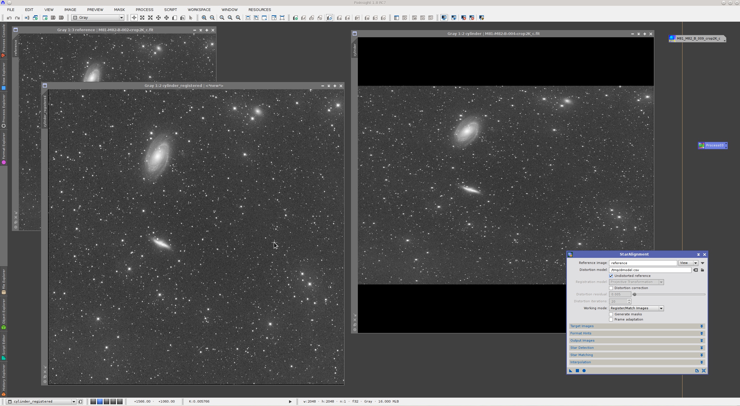
In this case, the undistorted model parameter has been enabled because the registration reference image has no distortion. With the help of a model, StarAlignment registers this image immediately. However, without a distortion model, the image shown in the screenshot above cannot be registered, even with local distortion corrections.
References
[1] Francisco G. Vald?s et al. (1995), FOCAS Automatic Catalog Matching Algorithms, Publications of the Astronomical Society of the Pacific, 107, pp. 1119?1128.
[2] M. Marszalek, P. Rokita (2004), Pattern Matching with Differential Voting and Median Transformation Derivation, Computer Vision and Graphics (Computational Imaging and Vision Series), 32, pp. 1002?1007.
[3] D. Lang, D. W. Hogg, K. Mierle, M. Blanton, and S. Roweis (2010), Astrometry.net: Blind astrometric calibration of arbitrary astronomical images, The Astronomical Journal (AJ), vol. 37, pp. 1782?2800.
[4] G.D. Evangelidis, C. Bauckhage (2011), Efficient and Robust Alignment of Unsynchronized Video Sequences, German Association for Pattern Recognition (DAGM) 2011, Frankfurt.
[5] Brown, D. C. (1966), Decentering Distortion of Lenses, Photogrammetric Engineering, vol. 32, No. 3, pp. 444?462.
[6] Martin A. Fischler, Robert C. Bolles (1981), Random Sample Consensus: A Paradigm for Model Fitting with Applications to Image Analysis and Automated Cartography, Communications of the ACM, Vol. 24 No. 6, pp. 381?395