Some time ago I published a little processing tutorial with a very nice and deep image of the M81/M82 region by Harry Page, using mainly the ATrousWaveletTransform tool (for noise reduction) and HDRWaveletTransform (for dynamic range compression). To put the following example in perspective, I strongly recommend you take a look at that tutorial on this forum post that I wrote in June.
We'll try now to achieve the same goals with the new MultiscaleMedianTransform tool. We'll use also the new HDRMultiscaleTransform tool, the successor to HDRWaveletTransform.
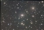
Let's start by loading the original, linear image:
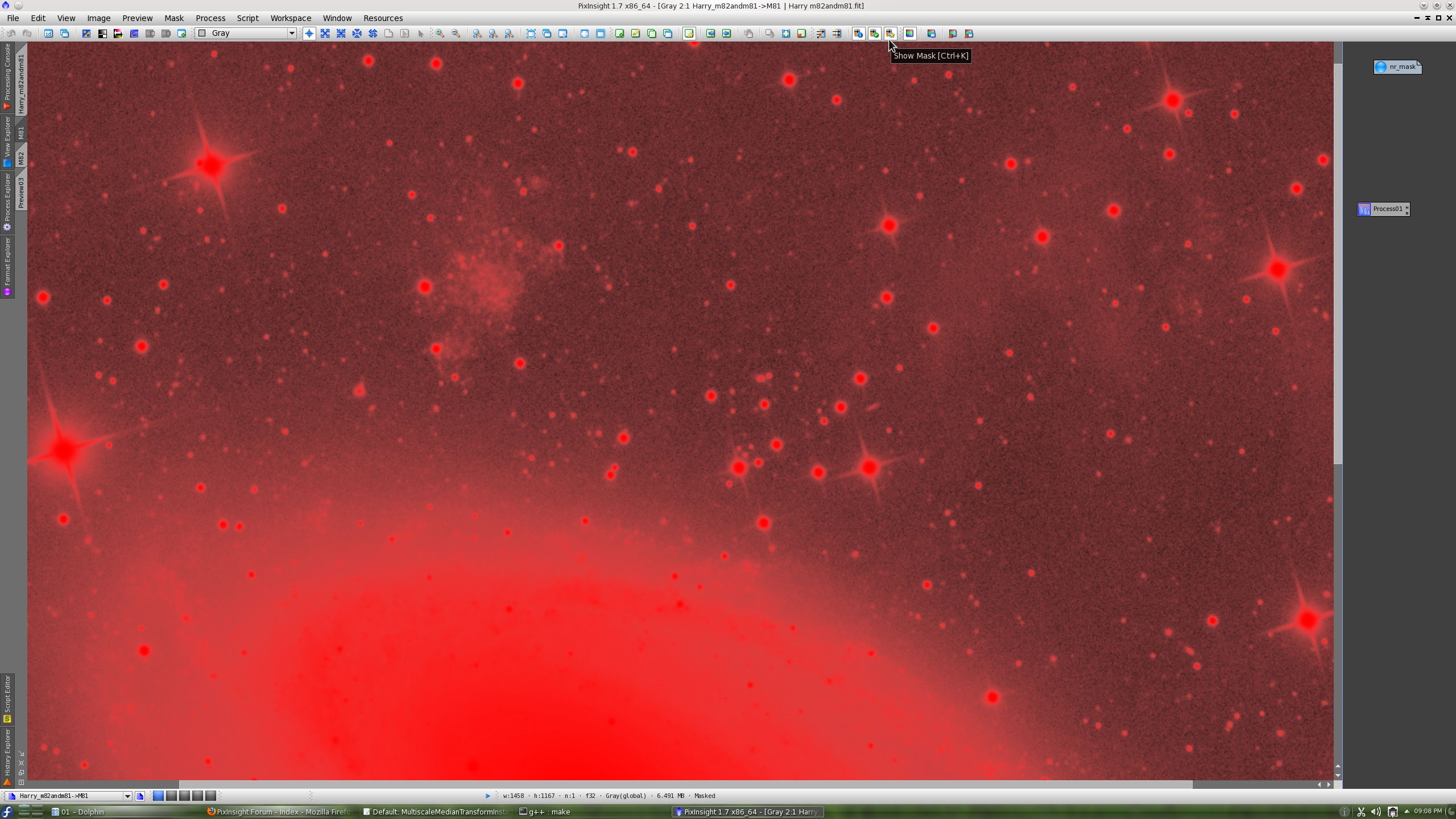
In this example we'll use a mask to apply noise reduction where it is more required. The mask will allow us to modulate noise reduction as a function of signal-to-noise ratio: the brightest, high-SNR areas will be protected while the dark, low-SNR regions such as the sky background and transitions between the sky and the objects will receive proportionally more noise reduction. In our example, the noise reduction mask is simply a stretched duplicate of the original image. In the following screenshot you can verify mask protection on a preview of interest.
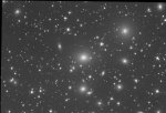
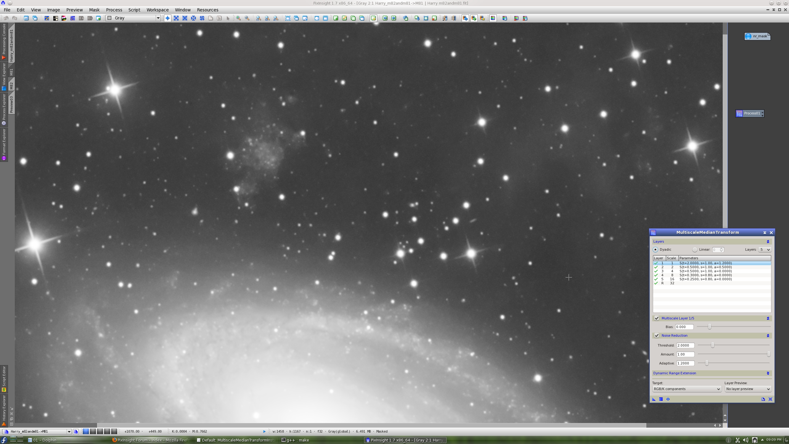
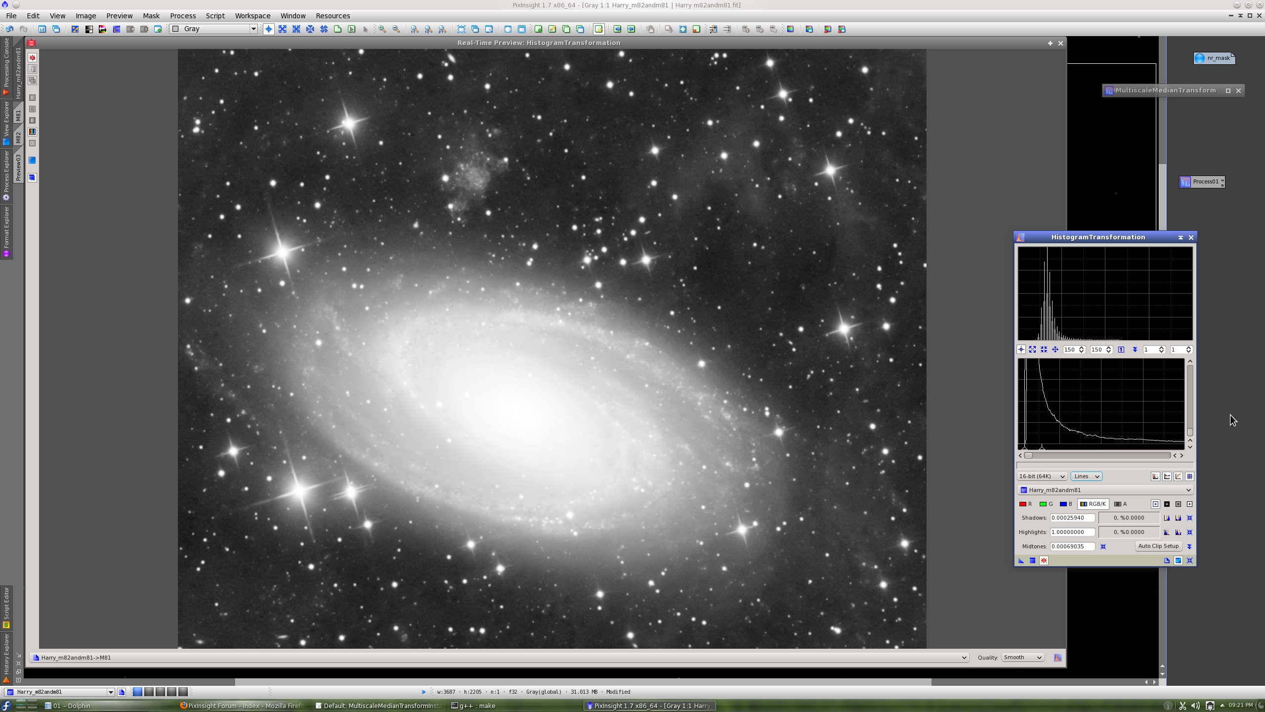
The mask has been stretched by transferring ScreenTransferFunction's AutoStretch settings to the HistogramTransformation tool. This is the same preview with mask visibility disabled:
Recall that we are working with the linear image; it is just the mask what we have stretched, and the image is visible on the screen thanks to the ScreenTransferFunction tool (STF).
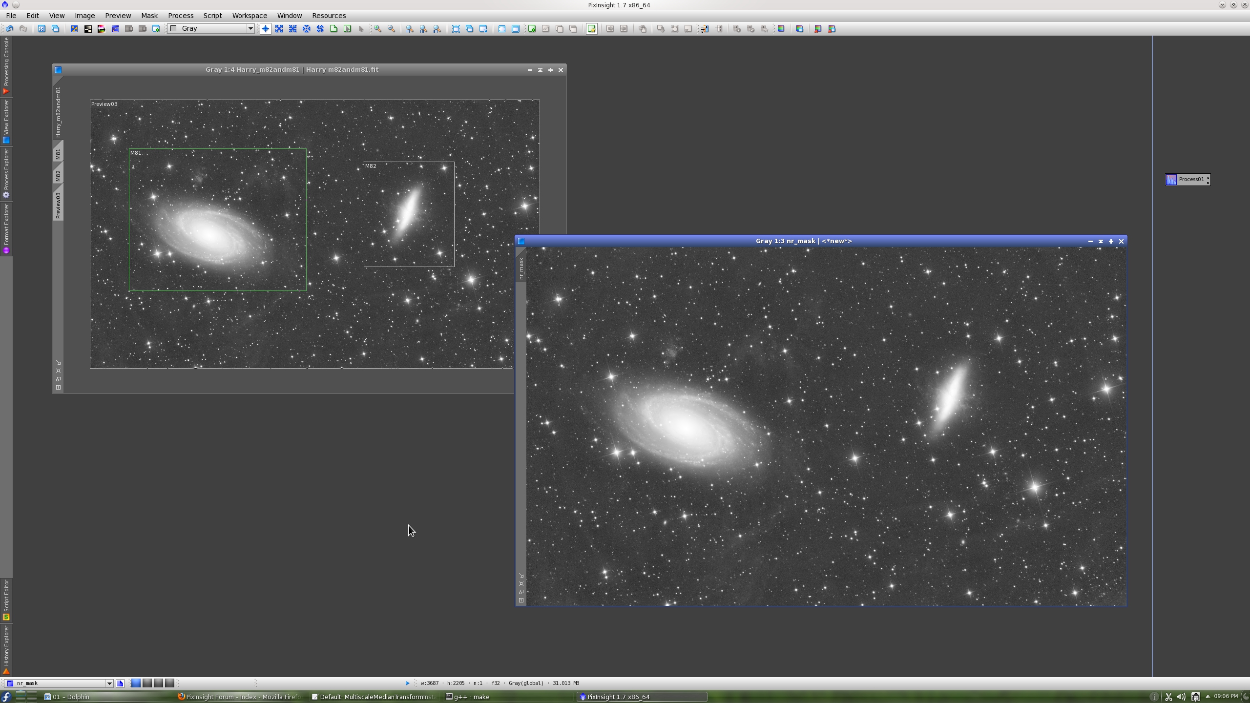
Now without more preambles, let's see MultiscaleMedianTransform in action:
To evaluate the result, you should see and compare the above two screenshots at full resolution (click on the thumbnail images in this post). I would say that the result is somewhat better than what we achieved with wavelets. It has been easier and more controllable too. Both the ATWT and MMT tools are particularly well suited for noise reduction in images like this one.
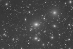
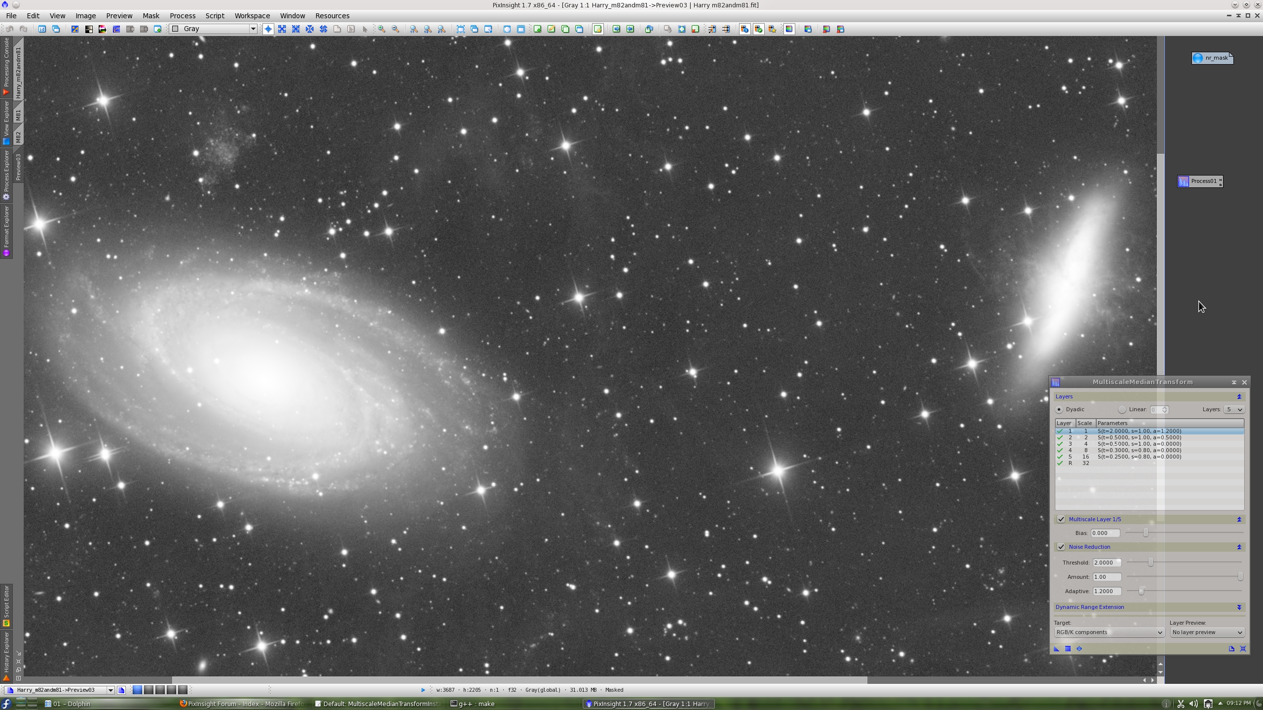
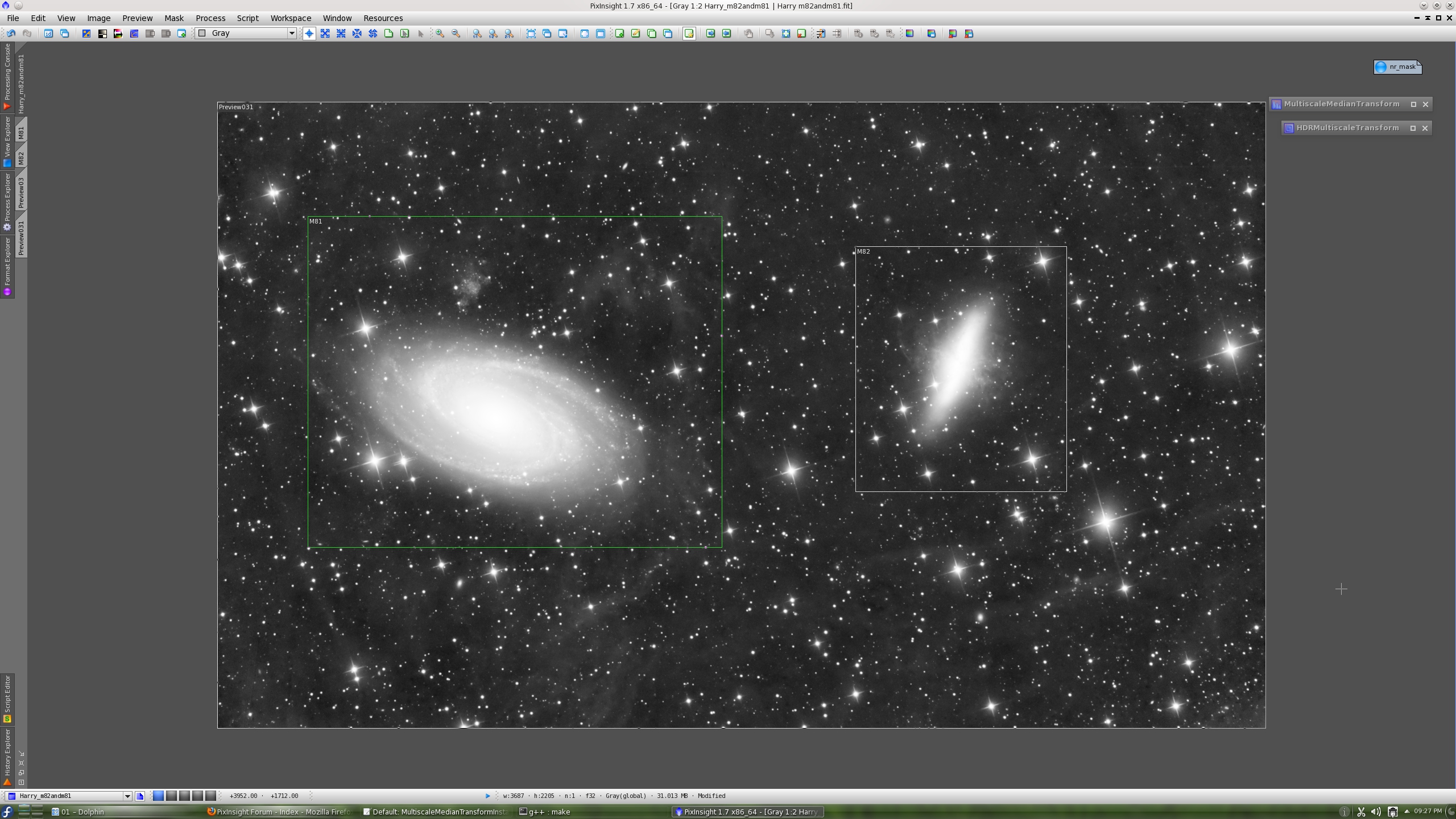
We repeat the same test with a larger preview covering both main objects. This is the original image:
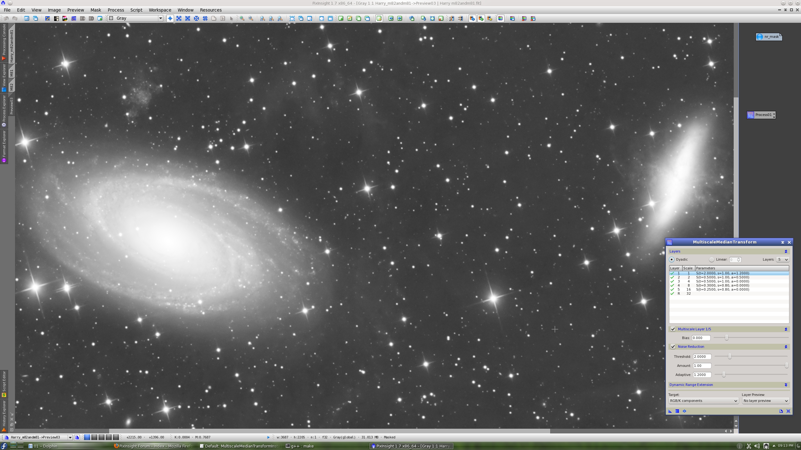
And this is after noise reduction with MMT:
After noise reduction, I want to introduce you the new HDRMultiscaleTransform tool. This is the successor to the HDRWaveletTransform tool, which will no longer be available as a standard PixInsight tool (the HDRWaveletTransform process will continue being available under the Compatibility category, however, to provide support for existing projects and scripts).
HDRMultiscaleTransform is exactly identical to HDRWaveletTransform, except that it now provides the possibility to select among two different transformations to perform the dynamic range compression task: the ? trous wavelet transform (as before) and the multiscale median transform. Other than this addition and a few minor bug fixes, the underlying HDR compression algorithm is the same one that was conceived and designed by PTeam member Vicent Peris several years ago. Don't worry, the good old things only change to be improved in PixInsight")
As you know, the current dynamic range compression tools in PixInsight only work with stretched images. This is the HistogramTransformation instance that we have applied:
and this is the resulting MMT-denoised and stretched image:
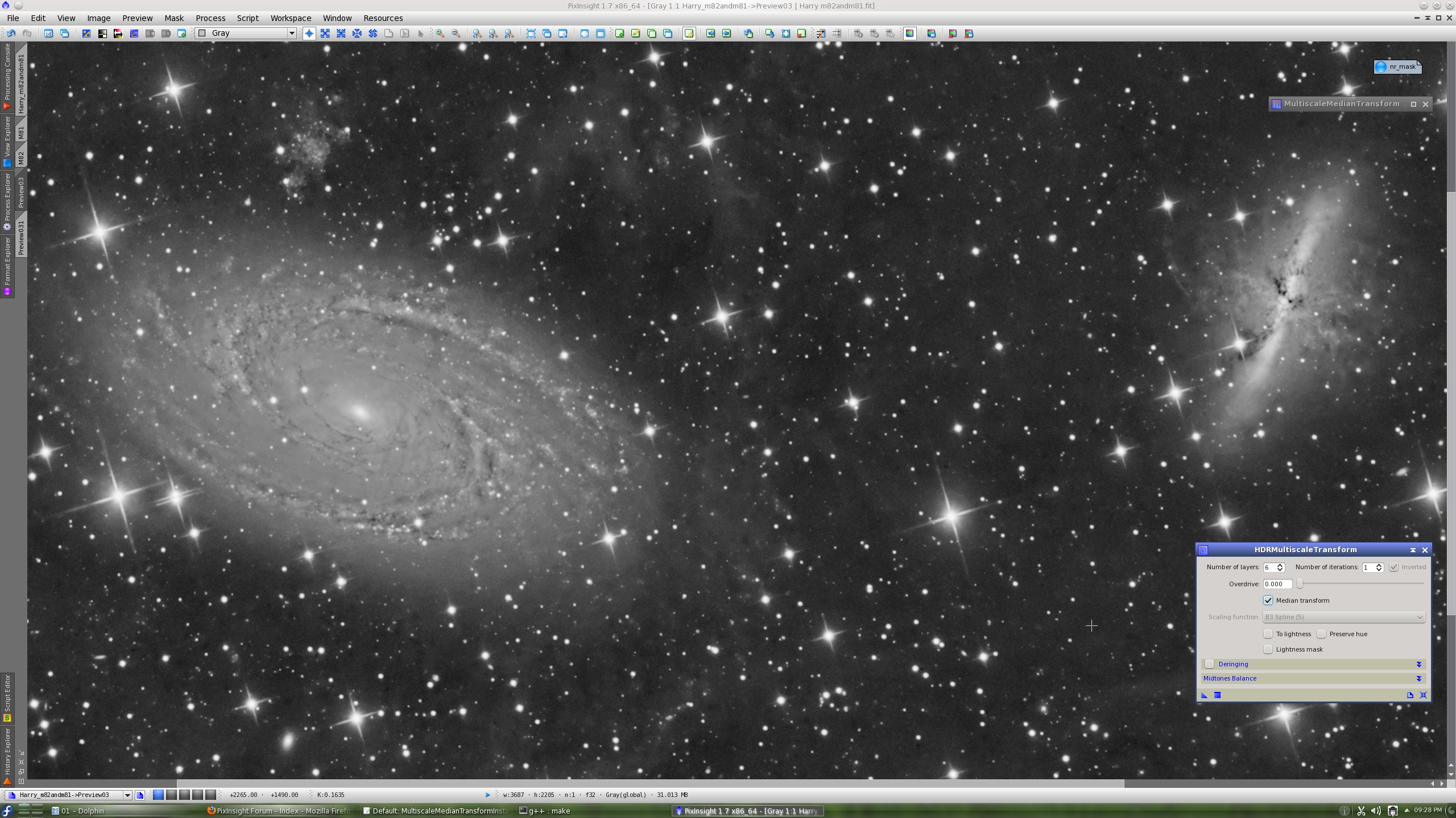
Here is the result after applying HDRMultiscaleTransform with a wavelet-based transform and five wavelet layers:
This is after HDRMultiscaleTransform with a median-based transform and six wavelet layers:
As you can see, the results achieved and the meaning of the layers parameter are very different. The median-based transform tends to be more aggressive at smaller scales. Is a median-based HDRMT better than a wavelet-based HDRMT? Not at all in our opinion; they are just different in their behavior and characteristic features, and achieve different goals. They provide different interpretations of the data, equally valid, as a result of different solution paths to the dynamic range compression problem.
As you might expect, the result of the median-based HDRMT has no ringing artifacts. This is a big improvement with respect to the wavelet-based result (compare the two screenshots above). This is a consequence of the absence of ringing in the multiscale median transform. However, you should keep in mind that the MMT has some drawbacks associated with the implemented structuring elements, mainly generation of artifacts around corners, which may also be present in median-based HDRMT processed images. We already have exemplified these problems in a previous tutorial.
The aggressiveness of median-based HDRMT in terms of overall contrast reduction can be controlled by simply working at larger dimensional scales. Below is the result with 8 median-based layers. Of course, there is no ringing.
Before HDRMT:
After HDRMT, median-based, 8 layers:
For completeness, this is the result after three iterations of the above HDRMT instance (with inverted iterations enabled):
Thanks again to Harry Page for allowing us to work with this wonderful image.
We'll try now to achieve the same goals with the new MultiscaleMedianTransform tool. We'll use also the new HDRMultiscaleTransform tool, the successor to HDRWaveletTransform.
Let's start by loading the original, linear image:
In this example we'll use a mask to apply noise reduction where it is more required. The mask will allow us to modulate noise reduction as a function of signal-to-noise ratio: the brightest, high-SNR areas will be protected while the dark, low-SNR regions such as the sky background and transitions between the sky and the objects will receive proportionally more noise reduction. In our example, the noise reduction mask is simply a stretched duplicate of the original image. In the following screenshot you can verify mask protection on a preview of interest.
The mask has been stretched by transferring ScreenTransferFunction's AutoStretch settings to the HistogramTransformation tool. This is the same preview with mask visibility disabled:

Recall that we are working with the linear image; it is just the mask what we have stretched, and the image is visible on the screen thanks to the ScreenTransferFunction tool (STF).
Now without more preambles, let's see MultiscaleMedianTransform in action:
To evaluate the result, you should see and compare the above two screenshots at full resolution (click on the thumbnail images in this post). I would say that the result is somewhat better than what we achieved with wavelets. It has been easier and more controllable too. Both the ATWT and MMT tools are particularly well suited for noise reduction in images like this one.
We repeat the same test with a larger preview covering both main objects. This is the original image:
And this is after noise reduction with MMT:
After noise reduction, I want to introduce you the new HDRMultiscaleTransform tool. This is the successor to the HDRWaveletTransform tool, which will no longer be available as a standard PixInsight tool (the HDRWaveletTransform process will continue being available under the Compatibility category, however, to provide support for existing projects and scripts).
HDRMultiscaleTransform is exactly identical to HDRWaveletTransform, except that it now provides the possibility to select among two different transformations to perform the dynamic range compression task: the ? trous wavelet transform (as before) and the multiscale median transform. Other than this addition and a few minor bug fixes, the underlying HDR compression algorithm is the same one that was conceived and designed by PTeam member Vicent Peris several years ago. Don't worry, the good old things only change to be improved in PixInsight
As you know, the current dynamic range compression tools in PixInsight only work with stretched images. This is the HistogramTransformation instance that we have applied:
and this is the resulting MMT-denoised and stretched image:
Here is the result after applying HDRMultiscaleTransform with a wavelet-based transform and five wavelet layers:

This is after HDRMultiscaleTransform with a median-based transform and six wavelet layers:
As you can see, the results achieved and the meaning of the layers parameter are very different. The median-based transform tends to be more aggressive at smaller scales. Is a median-based HDRMT better than a wavelet-based HDRMT? Not at all in our opinion; they are just different in their behavior and characteristic features, and achieve different goals. They provide different interpretations of the data, equally valid, as a result of different solution paths to the dynamic range compression problem.
As you might expect, the result of the median-based HDRMT has no ringing artifacts. This is a big improvement with respect to the wavelet-based result (compare the two screenshots above). This is a consequence of the absence of ringing in the multiscale median transform. However, you should keep in mind that the MMT has some drawbacks associated with the implemented structuring elements, mainly generation of artifacts around corners, which may also be present in median-based HDRMT processed images. We already have exemplified these problems in a previous tutorial.
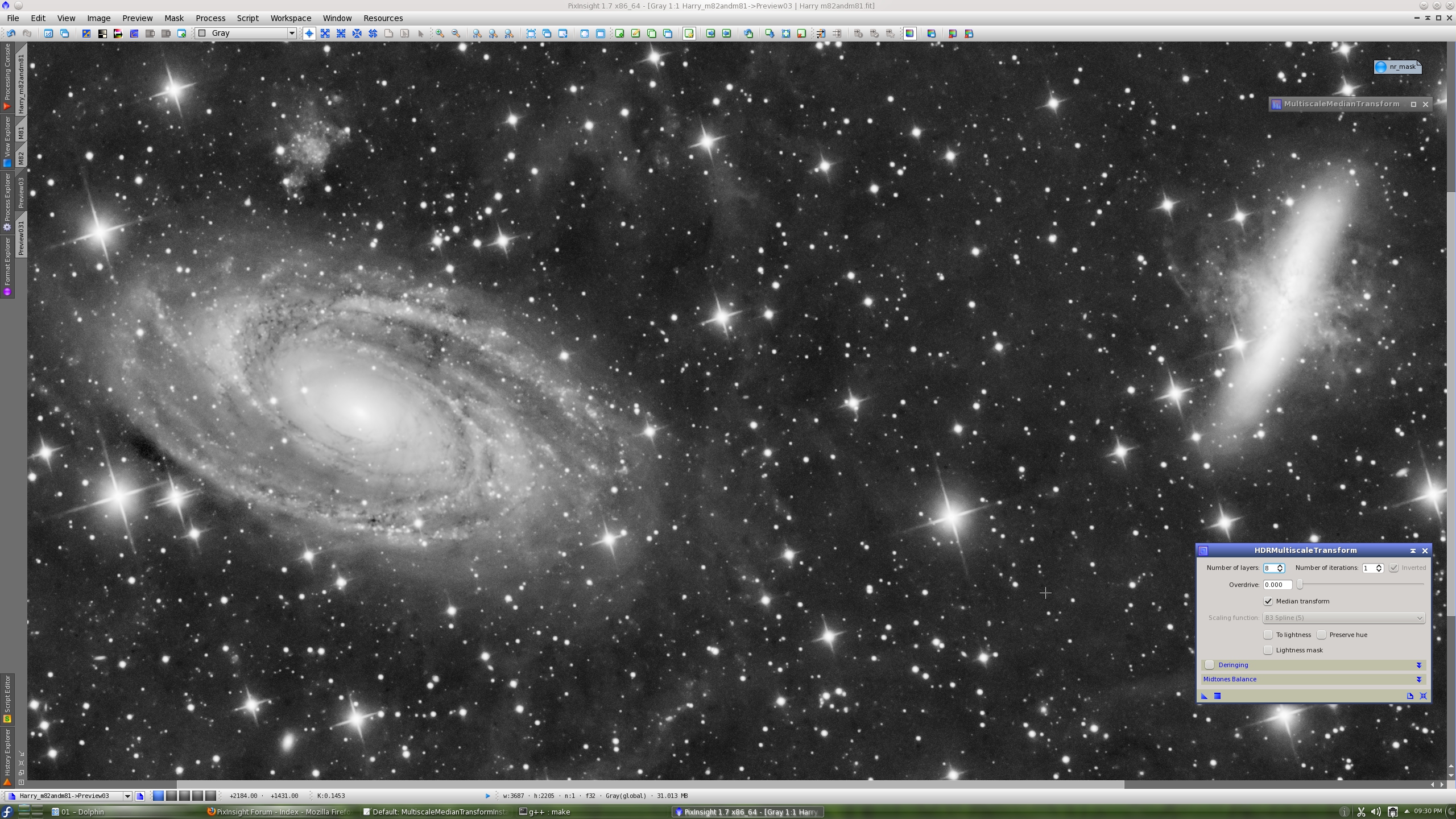
The aggressiveness of median-based HDRMT in terms of overall contrast reduction can be controlled by simply working at larger dimensional scales. Below is the result with 8 median-based layers. Of course, there is no ringing.
Before HDRMT:
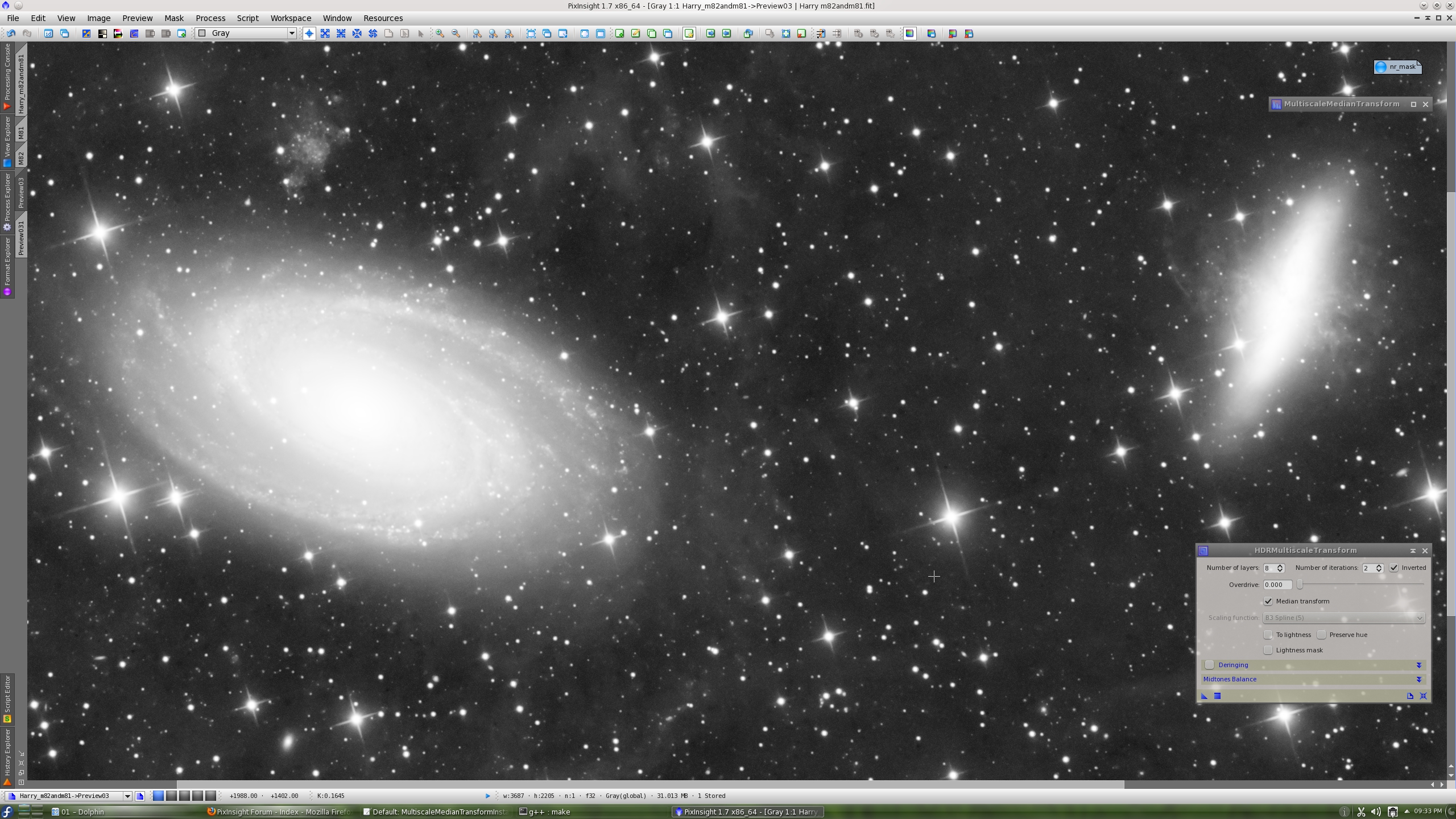
After HDRMT, median-based, 8 layers:
For completeness, this is the result after three iterations of the above HDRMT instance (with inverted iterations enabled):

Thanks again to Harry Page for allowing us to work with this wonderful image.