How many dark frames?

STEVE333

Well-known member
HOW MANY DARK FRAMES SHOULD I USE?
I've seen this question asked many times, and, the answers are always somewhat vague. No wonder, because, the answer depends on several factors that vary from user to user such as; Amount of Sky Glow (LP), Length of exposure, Camera Dark Current, etc.

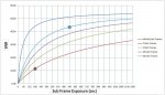
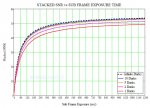
I've created an Excel worksheet that takes all of the various factors into account, and, presents a graph showing the final stacked SNR for 2, 5, 10, 20, and infinite Dark Frames. See first picture below.

The vertical axis of the graph is the relative SNR for the stacked images from a nights data collection. The horizontal axis is Sub Frame Integration Time (in other words, how long is your exposure for each image).  The actual SNR isn't important. What is important is if your choice of Sub Frame Integration Time and # of Dark Frames is maximizing your SNR. 
In the picture below there are two dots on the graph. [list type=decimal]
[*]The red dot indicates that collecting the data using a Sub Frame Exposure Time of 180 sec, and, processing the data with only 2 Dark Frames would yield a SNR of about 11.
[*]If 20 Dark Frames had been used to process the same 180 sec Sub Frames data the light-blue trace shows the SNR would have improved to about 29, a significant improvement.
[*]If the data were collected using 540 sec Exposures (rather than 180 sec Exposures) and 20 Dark Frames were used to process the data (the conditions for the blue dot) the SNR would be about 43.
[/list]
Again, the absolute value of the SNR is not important. What is important is to understand that a higher SNR on the graph means a better final image (lower noise). For example, this allows you to determine whether or not you need to collect more Dark Frames.
The graph in the first image is for my camera/telescope and LP/filter conditions. Your graph will be determined by your camera/telescope/LP etc.

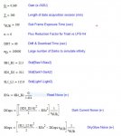
The worksheet (see second image) requires data from 2 Bias Frames, 2 Dark Frames and 2 Light Frames (Light frames MUST be registered to each other) all taken at the same ISO setting on the camera (I used ISO 800 for my Canon T3). The Light and Dark frames need to have the same Exposure Time (I used 180 sec for my data).

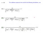
Each pair of RAW frames were loaded into Pixinsight and subtracted using PixelMath to create a Difference image. The Statistics process was then used to measure the stdDev of the Difference image with the units in the upper left corner of the Statistics window set to 14-bit to match my camera RAW output. You would change this to match your camera output. The result of doing this for all three sets of images will be: StdDev(Bias1-Bias2), StdDev(Dark1-Dark2) and StdDev(Light1-Light2). These values are entered into the Excel worksheet.
In addition you need to enter:
Total time to collect data =  the length of time you expect to be collecting data [time from the start of the first image till the end of the last image] (min).
t =   the exposure time for the Dark and Light frames used to measure the StdDev.
Dither and Download time =  the average time between the end of one image and the start of the next. Because of dithering and settling time there are about 60 seconds between my images.

If anyone is interested in the Excel worksheet just contact me with a PM and I'll be glad to send it to you.

Comments welcome.

Steve
 

Attachments

  • New Dark Frame Graph.JPG
    New Dark Frame Graph.JPG
    79.6 KB · Views: 295
  • Dark Frame Inputs.JPG
    Dark Frame Inputs.JPG
    60.1 KB · Views: 217
A little further explanation:
[list type=decimal]
[*]The Difference frame created by subtracting the two Bias frames allows the sensor Read Noise to be determined.
[*]The Difference frame created by subtracting the two Dark Frames, along with the knowledge of the Read Noise allows the Dark Current Noise to be determined. This allows the Dark Current to be determined.
[*]The Difference frame created by subtracting the two Light Frames, along with the knowledge of the Read Noise and Dark Current Noise allows the Sky Glow current to be determined.
[*]Having Read Noise, Dark Current, and Sky Glow Current, the predicted SNR for any Exposure Time can be calculated.
[*]The first three steps are pretty well know/documented in the literature. However, adding the effect Dither and download time and of Dark Frame Noise is not something I've seen before.
[*]Having Total time to collect data along with Sub Frame Exposure & Dither and download time the total number of exposures can be calculated.
[*]The noise in the stacked images will be the noise is a single image / sqrt(total number of exposures).
[*]The effect of the Dark Frame Noise is different. The noise in a single Dark Frame is

        sqrt[(Read Noise)^2 + (Dark Current Noise)^2].

If there are N Dark Frames combined to create the Master Dark, then the noise of the Master Dark will be the (noise of a single Dark Frame) / sqrt(N).
[*]Assuming a single Master Dark Frame is used to correct each Light image, when the Lights are combined (stacked) the Dark Frame Noise won't be reduced at all because it is the same in every Light Frame. Thus Dark Frame Noise can only be reduced by increasing the number of Dark Frames combined to make the master.
[/list]
All of these calculations are included in the calculation of the graphs shown at the beginning of this post.

Hope this helps for anyone interested in more details.

Steve
 
In your charts, what is your signal?  In other words, what are you graphing the SNR of?  A star, a faint nebula, the skyglow or what?

Mark
 
sharkmelley said:
In your charts, what is your signal?  In other words, what are you graphing the SNR of?  A star, a faint nebula, the skyglow or what?

Mark

Hi Mark -

First, thanks for taking the time to look into this.

Ironically, discussing the Signal was on my mind this morning as I was waking up. I was planning on explaining about the Signal in a REPLY this morning. You "beat me to the punch".

You are correct in catching that no mention os Signal has been made. The short answer is I've assumed an arbitrary Signal of 1 ADU/sec.

As you correctly pointed out previously, if the Shot Noise in the Signal is included in the SNR calculations (as is usually and correctly done) then calculations must be carried out in electrons, not in ADU. However, for low level signals where the Shot Noise in the Signal is not significant, calculations using either electrons or ADU units will yield the same result. I take advantage of this fact by neglecting the Shot Noise in the Signal in my calculations. Rather than 1 ADU/sec I could have chosen 0.0001 ADU/sec so that the Shot Noise really would be insignificant. However, in my equations, changing the Signal Level simply scales the final stacked SNR. It doesn't alter the shape or relative amplitudes of the calculated curves.

I hope this makes sense.

Cheers,

Steve

 
I'm sorry to be the one who tells you that those graphs make no sense at all.

For 180sec exposures, you have stated that the standard deviations for skyglow, dark current and bias are 115.9, 30.1, 22.3 respectively.  I have no reason to doubt those figures.

It is therefore quite clear that skyglow is the main source of noise by quite a large margin.  If you could remove the dark noise completely then skyglow noise remains and you would obtain a marginal reduction in overall noise.  But the graph indicates a reduction in noise a factor of 4 for infinite darks at 180sec.  It's completely impossible, given your original standard deviation figures.

Mark
 
sharkmelley said:
I'm sorry to be the one who tells you that those graphs make no sense at all.

For 180sec exposures, you have stated that the standard deviations for skyglow, dark current and bias are 115.9, 30.1, 22.3 respectively.  I have no reason to doubt those figures.

It is therefore quite clear that skyglow is the main source of noise by quite a large margin.  If you could remove the dark noise completely then skyglow noise remains and you would obtain a marginal reduction in overall noise.  But the graph indicates a reduction in noise a factor of 4 for infinite darks at 180sec.  It's completely impossible.

Mark

Hi Mark - Let me clear up the confusion.

For a single frame the skyglow noise is much greater than the Dark Noise from the Master Dark. However, as more and more frames are stacked the skyglow noise (along with dark noise and Read noise in the Light images) are reduced by sqrt(number of stacked frames). Because the Master Dark Frame noise isn't reduced by the stacking of the Light frames, this noise can be significant when compared to the reduced noise in the stacked images.

As explained in the text, the vertical axis of the graph shows the Stacked SNR (SNR for the stacked images). Unfortunately I omitted "Stacked" in the vertical axis label which may have led to the confusion.

Steve


is it true though that the noise is reduced? as N increases the signal goes up linearly and the noise also increases, but by sqrt(N). therefore the SNR goes as N/sqrt(N) or sqrt(N). but both the noise and the signal are increasing as N increases.

rob
 
STEVE333 said:
sharkmelley said:
I'm sorry to be the one who tells you that those graphs make no sense at all.

For 180sec exposures, you have stated that the standard deviations for skyglow, dark current and bias are 115.9, 30.1, 22.3 respectively.  I have no reason to doubt those figures.

It is therefore quite clear that skyglow is the main source of noise by quite a large margin.  If you could remove the dark noise completely then skyglow noise remains and you would obtain a marginal reduction in overall noise.  But the graph indicates a reduction in noise a factor of 4 for infinite darks at 180sec.  It's completely impossible.

Mark

Hi Mark - Let me clear up the confusion.

For a single frame the skyglow noise is much greater than the Dark Noise from the Master Dark. However, as more and more frames are stacked the skyglow noise (along with dark noise and Read noise in the Light images) are reduced by sqrt(number of stacked frames). Because the Master Dark Frame noise isn't reduced by the stacking of the Light frames, this noise can be significant when compared to the reduced noise in the stacked images.

As explained in the text, the vertical axis of the graph shows the Stacked SNR (SNR for the stacked images). Unfortunately I omitted "Stacked" in the vertical axis label which may have led to the confusion.

Steve

I'm afraid your response really doesn't clear up the confusion at all.  I stand by my comments above because you haven't addressed them. 

I would be interested if you can explain (preferably with a calculation) why you think that for a sub frame exposure of 180sec the top blue line has 4x the (Stacked) SNR of the red line i.e approx. 45 vs approx. 12 because I think you are making a fundamental error somewhere.  The skyglow is the main source of noise in that 180sec sub and even if you could magically eliminate the dark noise and bias noise from the sub you simply cannot get a 4x improvement keeping the sub length at 180sec.

Mark
 
pfile said:
is it true though that the noise is reduced? as N increases the signal goes up linearly and the noise also increases, but by sqrt(N). therefore the SNR goes as N/sqrt(N) or sqrt(N). but both the noise and the signal are increasing as N increases.

rob

That's right Rob. However, the stacked image is always divided by the number of frames added in order to "normalize" the result. In other words, if 16 frames were stacked, then the resulting stacked image would be divided by 16. This keeps the signal the same for the stack as for one frame, but, the noise for the stack will be reduced by sqrt(16). That's why the phrase "stacking reduces the noise" is so common.

Make sense?

Steve
 
sharkmelley said:
STEVE333 said:
sharkmelley said:
I'm sorry to be the one who tells you that those graphs make no sense at all.

For 180sec exposures, you have stated that the standard deviations for skyglow, dark current and bias are 115.9, 30.1, 22.3 respectively.  I have no reason to doubt those figures.

It is therefore quite clear that skyglow is the main source of noise by quite a large margin.  If you could remove the dark noise completely then skyglow noise remains and you would obtain a marginal reduction in overall noise.  But the graph indicates a reduction in noise a factor of 4 for infinite darks at 180sec.  It's completely impossible.

Mark

Hi Mark - Let me clear up the confusion.

For a single frame the skyglow noise is much greater than the Dark Noise from the Master Dark. However, as more and more frames are stacked the skyglow noise (along with dark noise and Read noise in the Light images) are reduced by sqrt(number of stacked frames). Because the Master Dark Frame noise isn't reduced by the stacking of the Light frames, this noise can be significant when compared to the reduced noise in the stacked images.

As explained in the text, the vertical axis of the graph shows the Stacked SNR (SNR for the stacked images). Unfortunately I omitted "Stacked" in the vertical axis label which may have led to the confusion.

Steve

I'm afraid your response really doesn't clear up the confusion at all.  I stand by my comments above because you haven't addressed them. 

I would be interested if you can explain (preferably with a calculation) why you think that for a sub frame exposure of 180sec the top blue line has 4x the (Stacked) SNR of the red line i.e approx. 45 vs approx. 12 because I think you are making a fundamental error somewhere.  The skyglow is the main source of noise in that 180sec sub and even if you could magically eliminate the dark noise and bias noise from the sub you simply cannot get a 4x improvement keeping the sub length at 180sec.

Mark

Mark - Here are the equations.

The first attachment below shows the equations used to calculate the Read Noise in electrons (RNe), the Dark Current in electrons/sec (DCeps) and the Skyglow in electrons/sec (SGeps).
  • The "Flux Reduction Factor" is not related to this discussion (I'm using it to approximate the reduction in skyglow when switching to the Triad filter) but I've left it in because it does affect the results and I wanted you to see the same final numbers.
  • tSUB is the exposure time used for the Dark and Light frames used to calculate RNe, etc.
  • DDT is the Drift & Download Time, ie, the average time from the end of one image till the start of the next image. This "wasted time" does affect the final curves so I've left it in for this discussion.

The second attachment shows how the noise terms are combined to calculate the SNR.
  • Since you question revolved around the 180 sec sub frame exposure, t = 180.
  • The first equation shows the SNR for a single frame (no Dark Frame noise included yet). The numerator is the Signal where a signal flux of 1 ADU/sec is assumed.  The denominator sums the Read Noise, the SkyGlow Noise and the Dark Current Noise. A single frame is seen to have SNR = 4.7.
  • The second equation includes the noise reduction achieved by combining multiple images (still no Dark Frame noise included yet). This stacked SNR = 44.1 which is the value of the top blue line in the graph for the 180 sec subframe exposure.
  • The last equation is similar to the second with the addition of the Dark Frame Noise term in the denominator. The numerator of this added term is the Dark Noise of a single Dark Frame. The 2 in the denominator of this added term is the number of Dark Frames added to create the Master Dark Frame. I used 2 because that is the number of dark frames represented by the Red curve in the graph. Notice that the Dark Frame term is NOT reduced by the total number of Light frames, because, the identically same noise from the Master Dark Frame is added to every Light frame during calibration, and, combining frames only reduces RANDOM NOISE.  The stacked SNR = 11.5 which is the value for the blue dot on the graph.

I hope this explains the 4X difference between the Red curve and the top Blue curve for the 180 sec subframe exposure.

Steve
 

Attachments

  • MCAD Analysis.JPG
    MCAD Analysis.JPG
    51.8 KB · Views: 54
  • MCAD Results.JPG
    MCAD Results.JPG
    35.3 KB · Views: 59
STEVE333 said:
Mark - Here are the equations.

Thanks - I've worked through the equations and I can now see exactly what you are doing.  You'll be pleased to know I can't fault your logic!

Just as you said, the key issue is that the master dark is being subtracted from all light frames and hence the noise in the master dark appears in exactly the same place in each light frame and exactly the same place in the final stack.  Your equations and graphs correctly reflect this.

However, there is one important assumption you are implicitly making - you are assuming that no registration of light frames is required i.e. the star field lines up precisely in all the light frames taken over the 6 hour period.

In practice this simple case is unlikely because dithering is performed during acquisition or there is an accidental frame to frame drift.  In either case, registration of the images will be required before stacking and this will have the effect of randomising the position of the dark master noise across the stacked images and so noise reduction does take place because it is random.

So although your analysis is entirely correct, you are actually analysing a pathological case that almost never happens in practice.

Mark
 
sharkmelley said:
STEVE333 said:
Mark - Here are the equations.
However, there is one important assumption you are implicitly making - you are assuming that no registration of light frames is required i.e. the star field lines up precisely in all the light frames taken over the 6 hour period.

In practice this simple case is unlikely because dithering is performed during acquisition or there is an accidental frame to frame drift.  In either case, registration of the images will be required before stacking and this will have the effect of randomising the position of the dark master noise across the stacked images and so noise reduction does take place because it is random.

So although your analysis is entirely correct, you are actually analysing a pathological case that almost never happens in practice.

Mark

Thanks for reviewing this Mark.

I think you are absolutely correct about the randomizing of the Dark Frame Noise caused by Dithering (or just frame-to-frame drift). I completely missed that! It seems that good dithering would completely randomize the Dark Frame Noise.

Would you think the modified equation shown in the first attachment properly accounts for the Dark Frame Noise when dithering is present? In the equation nD is the number of Dark Frames stacked to make the Master Dark Frame.

The second attachment shows the Stacked SNR graph without the randomizing effects of Dithering (or frame-to-frame drift) included. 

The third attachment shows the Stacked SNR graph with the complete randomizing effects of Dithering included (per the equation in the first attachment). The dithering makes a huge difference for the better.

Thanks again for your inputs and insight.

Steve
 

Attachments

  • Darks with Dither.JPG
    Darks with Dither.JPG
    16.9 KB · Views: 86
  • New Dark Frame Graph.JPG
    New Dark Frame Graph.JPG
    79.6 KB · Views: 82
  • Dither Graph.JPG
    Dither Graph.JPG
    87.3 KB · Views: 111
STEVE333 said:
Would you think the modified equation shown in the first attachment properly accounts for the Dark Frame Noise when dithering is present? In the equation nD is the number of Dark Frames stacked to make the Master Dark Frame.

The second attachment shows the Stacked SNR graph without the randomizing effects of Dithering (or frame-to-frame drift) included. 

The third attachment shows the Stacked SNR graph with the complete randomizing effects of Dithering included (per the equation in the first attachment). The dithering makes a huge difference for the better.

Your new equation look correct to me and the new graphs are much more in line with what I expect to see.  I think most of us take dithering for granted because it makes such a big difference.  Because of that, your initial results (without dithering)were quite counterintuitive.

Mark
 
Thanks Mark -

Your help is much appreciated.

I also use Dithering and can't imagine imaging without it.

When my new Triad filter arrives it will hopefully allow for 9 min exposures (rather than the 3 min exposures I'm limited to now) which will make the 1 min between exposures (time for my Dither to settle) less of a burden.

Steve
 
Always entertaining watching math guys spend more time debating a concept than actually just taking care of the issue. You can take 50, 180 second, darks in 2.5 hours + download time. I shoot three exposure times, 1800 secs, 600 secs, and 300 secs. I put my camera in a dark room in my house for a little less than two days and banged out 50 darks each plus about 100 bias. No one have two cloudy days to do that?
 
In references like the university course Modern Observational Techniques or the Lowell Observatory Exposure Time Calculator (at the bottom of the page there is a short documentation as a PDF file) some of the noise terms are weighted by an aperture term. In this discussion, every noise term has the same weight, implying a single-pixel aperture. If this happens here for simplification reasons, I have to express my worries:

What is the purpose of dithering? Besides better outlier rejection, it tries to "break the correlation" of noise sources which have spatial correlations. These noise sources live in the spatial domain and have a typical correlation length l. Such a length term (or an estimate of it) must be present somewhere in the formulas. Remember, in practice we have good dithering if we pick a random direction angle and a random length d with d>l.

In other words, with dithering we benefit from randomization in the spatial domain because we live in the imperfect world of Bayer matrices and confined between the bars of CCD columns. A single-pixel approach forgets about any such spatial correlations. Somewhere a term with units of length should be present, and (in my opinion) even if we don't account for dithering.

I'll end my math/theoretical mumble with the notes of another course. Lecture 5 may be of interest! My experimentalist part of self agrees with Charles, it takes less time doing it than think about it :laugh:
 
dld said:
Remember, in practice we have good dithering if we pick a random direction angle and a random length d with d>l.

Light pollution contribution to sky glow has such a large correlation length and that's why it is difficult to get rid of it with dithering. This also means it is smooth enough ("predictable" within our field of view) and we can use this observation for our benefit. With many light frames we can use an interpolation method and build a good DBE map to subtract from our data and make do even under light-polluted skies.
 
CharlesW said:
Always entertaining watching math guys spend more time debating a concept than actually just taking care of the issue. You can take 50, 180 second, darks in 2.5 hours + download time. I shoot three exposure times, 1800 secs, 600 secs, and 300 secs. I put my camera in a dark room in my house for a little less than two days and banged out 50 darks each plus about 100 bias. No one have two cloudy days to do that?

My wife had a good laugh when I read your response!

You'll be glad to know that I captured three days of darks (all at 540 secs) while debating this concept.  Having a Physics background is a curse. There is just something about "knowing" how something works. The pleasure when it's done is kind of like how good it feels when you quit hitting yourself in the head.

Steve
 
dld said:
In references like the university course Modern Observational Techniques or the Lowell Observatory Exposure Time Calculator (at the bottom of the page there is a short documentation as a PDF file) some of the noise terms are weighted by an aperture term. In this discussion, every noise term has the same weight, implying a single-pixel aperture. If this happens here for simplification reasons, I have to express my worries:

What is the purpose of dithering? Besides better outlier rejection, it tries to "break the correlation" of noise sources which have spatial correlations. These noise sources live in the spatial domain and have a typical correlation length l. Such a length term (or an estimate of it) must be present somewhere in the formulas. Remember, in practice we have good dithering if we pick a random direction angle and a random length d with d>l.

In other words, with dithering we benefit from randomization in the spatial domain because we live in the imperfect world of Bayer matrices and confined between the bars of CCD columns. A single-pixel approach forgets about any such spatial correlations. Somewhere a term with units of length should be present, and (in my opinion) even if we don't account for dithering.

I'll end my math/theoretical mumble with the notes of another course. Lecture 5 may be of interest! My experimentalist part of self agrees with Charles, it takes less time doing it than think about it :laugh:

Hi did -

1)
  • I looked at the articles you referenced (thanks for sharing those). All of those articles are related to the specific task of measuring the brightness of a single star. I believe you will find that the "aperture" they refer to is related to the size of the star image they are trying to measure. The "aperture" (actually a software aperture to eliminate signal outside of the star) is only used to determine how many pixels will be summed up to yield the brightness of the star. Thus the noise they are interested in is the noise of the summed pixels, not the noise in one pixel.
  • In other words, they have the same noise analysis we were discussing, but, they add the mathematics to determine how many pixels they will have to sum to accurately measure the star brightness, and, determine the noise when those pixels are summed.
  • I don't believe this "aperture" is relevant to my analysis of the noise in each individual pixel.
2) I'm not aware of any spatial coherence of the noise. As far as I am aware, the noise in each pixel is independent of the noise in any other pixel no matter how close or far apart the pixels are. I've never seen any "spatial coherence" term included in any of the other noise analyses. However, if I'm wrong I would be interested in learning about such a phenomenon.

Thanks for taking the time to respond.

Steve
 
Hello Steve, and thank you for the reply,

For (2) consider the bias frames of a DSLR. If we blink (with PI) some bias frames we will notice an underlying fixed pattern and (at least for my Canon cameras) horizontal bands which significantly differ from frame to frame. This is correlated noise, meaning that while random, it has structure, with a large correlation length across the horizontal direction. That's the reason we see horizontal bands: while random, in each instance (realization) it is more likely to see similar values across the horizontal axis than the vertical axis.

For (1) I will have to think about it  :laugh:

I'll be glad to hear what others think about the subject (preferably with references)! Thanks again!
 
Back
Top