Diffraction spikes rotation on Alt-Az telescope

Chilescope

Member
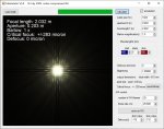
Hi, All! There is a well known problem with diffraction spikes rotation on Alt-Az telescopes. The field rotation is compensated by de-rotator but spikes not (we need to rotate whole tube to compensate). The amount of rotation increases with altitude of the object and with exposure time of course. Sigma clipping does not help.
Can somebody recommend the technique to minimize this effect during processing?
Also can I ask to create special script or procedure to deal with that?
On the image attached on the left side you can see this effect
spikes.jpg
 
Welcome to PixInsight Forum. There is no valid software-based solution to this problem. You'll have to search for a hardware-based solution, such as curved spider vanes to minimize diffraction artifacts by maximizing energy dispersion. The manufacturer of this telescope (ASA) will be able to provide a solution of this kind.
 
Juan, thanks for reply! Unfortunately I don't think it is possible to change the spider on 1m telescope. Could you please ask Pix team is it possible in principle to generate kind of tool to minimize this effect using software.
Thanks
 
As you have discovered, there is no way to reject these artifacts statistically, i.e. by image integration using pixel rejection algorithms. This happens because the artifacts are located on different locations in each frame. In other words: the artifacts replace pixels for which there are no observational data available in the data set.

An apparent 'solution' would be some kind of automated pixel replacement process, similar to a clone stamp tool. Irrespective of the way these techniques are implemented (morphological analysis, feature detection, trained neural networks, etc), they cannot be valid solutions: Nonexistent data are going to be replaced with invented data for aesthetic reasons without a documentary basis, which is painting, not image processing as we understand it.

This is a good example of the kind of problems where a software-based solution cannot exist: There is no way to replace observational data that have not been acquired.

I don't think it is possible to change the spider on 1m telescope

Replacing the spider shouldn't be strictly necessary. Although replacing straight vanes with curved ones is probably the best solution, there exist other ways to spread the diffracted energy throughout the entire image using special masks. This should be quite easy to implement.
 
Those are curved spider vanes, which are probably the best solution available. I understand that replacing the straight vanes of a 1-meter telescope with curved ones can be difficult, in both the technical and economic senses.

There are other solutions consisting of masks placed in front of existing straight vanes. For example, I've found this article that looks interesting.
 
Yes, interesting article about masks. Probably the most efficient solution. Only need to design the curve. 30 min work on CNC or 3D printing
Thanks
 
How much obstruction has increased? These masks look relatively wide. These ones look more compact means less obstruction
 

Attachments

  • Anti6.gif
    Anti6.gif
    4.2 KB · Views: 47
That is a good observation! I scaled mine in the vertical direction because I needed to cover the combined thickness of the vane and the usb cable. The idea is that there is no preferred direction, so there needs to be a total cover. I did not calculate the extra obstruction but in relation to the total image area it will not be that much. The article Juan linked to talks about 7% of area obstruction for this type of element, which is not that much.
Having said that, you can easily use a thinner pattern (as in the original stl file from thingiverse) if you just need to cover the vanes.
Once you have the 3D drawing, you can 3D print and experiment. I cannot tell you if if the pattern you attached is ideally suited for smooth 3D printing because of the very pointy ends that need accurate figuration.
 
annehouw, did I get you right I can scale down the thickness of the mask to say 40mm (max) just to cover the vanes and keep the length say 400mm?
But in this case the proportions and curve of mask will be changed. Will it work fine anyway?
 
No, not without a effectiveness penalty, as you are introducing a preferred direction again by deviating from circle elements (see original article).
I measured mine: I have a length of 12cm and the widest part is 3cm. This is very, very close to the original design ratio.
With a big scope as yours, with a single vane of 400mm, you would have a maximimum width of 100mm (so much wider than the max of 40mm you are looking at). In my personal opinion, the amount of light obstruction is not the main thing to worry about. It is very, very small. What should be thought of is a very sturdy attachment of these "wings" to the spiders. You do not want to have them fall on your mirror. If you look at the thingiverse design, they have attachment clips included, but I made sure that they were taped to the vanes as well, very securely.

There is one other thing that needs mentioning. Everything in the light path diffracts light. Also curved vanes and these little gadgets. These last two diffract the light in all directions, causing a slight loss of contrast. How much, I do not know, but I do not believe it is very noticable.
No free lunch, unfortunately, but a trade-off.
 
Got it, thanks a lot!
Another problem I have found we have triangle vanes on 1m telescope. So if we install the masks as it is they will be not perpendicular to the optical axis. Is this critical (the curve of the mask will change in projection)?
If it is critical we should design kind of spacer to level the mask perpendicular
 
Interesting question. The answer is that I do not know how critical this is (depends on the angle of your vanes to the optical plane).
One way correct for this would be to do a projection-perspective correction on your design. If you measure the angle of the vane to the optical plane, this would just be a mathematical correction. It will not be perfect however, because the masks have a thickness (which you could also correct for in projection, but that is more complicated). Depending on the projection angle and the thickness of your mask, this last effect might not be noticable, but I do not know.

The idea of a spacer might be a good one. You could design this spacer also as a support structure to help you in attaching the masks to the vanes in a secure way.
 
That looks like a nice, simple to manufacture design. Interested to see how it works in practice!
On a side note: I had a look at your 1m telescope. Turns out it has the same designer and mirror manufacturer as the little brother I have in my backyard ;-)
 
That looks like a nice, simple to manufacture design. Interested to see how it works in practice!
On a side note: I had a look at your 1m telescope. Turns out it has the same designer and mirror manufacturer as the little brother I have in my backyard ;-)
Interesting)) Could you drop the link to look at brother?))
 
Well, it has the same designer (dr Keller) and the same mirror manufacturer (LOMO), but it is more a little brother from another mother. ;)
It is a 340mm Hypergraph (modified Cassegrain design)
hypergraph.jpg


It has a 3m focal point at the back (f/9) and a 1m focal point at the front (f/3). To achieve this the scope has corrector lenses (Wynne, I believe) at the back and a three element corrector lens assembly at the front. So, there is a 140mm triplet equivalent at the front, very sturdy and weighing a ton. The whole scope is about 42kg. To change from f/3 to f/9, the only thing to change is to put the secondary mirror in the holder at the front of the lens assembly.
99.9% I use it at f/3. Collimation of the secondary at f/3 is..hmmmm let me say...challenging :eek:
The camera is at the front (so on the left side in this drawing) and the power cable and USB cable have to cross the front. Normally attached to a spider, making one spider arm thicker than the other ones, so that is why I experimented with those masks.
I use f/3 as a brute force solution to overcome Bortle 5 skies and it does work if you dedicate the hours as well.
There are a few of these scopes in existence (they were made to order). dr Keller does not make these "little" scopes anymore as far as I know.
 
Last edited:
Well, it has the same designer (dr Keller) and the same mirror manufacturer (LOMO), but it is more a little brother from another mother. ;)
It is a 340mm Hypergraph (modified Cassegrain design)View attachment 8190

It has a 3m focal point at the back (f/9) and a 1m focal point at the front (f/3). To achieve this the scope has corrector lenses (Wynne, I believe) at the back and a three element corrector lens assembly at the front. So, there is a 140mm triplet equivalent at the front, very sturdy and weighing a ton. The whole scope is about 42kg. To change from f/3 to f/9, the only thing to change is to put the secondary mirror in the holder at the front of the lens assembly.
99.9% I use it at f/3. Collimation of the secondary at f/3 is..hmmmm let me say...challenging :eek:
The camera is at the front (so on the left side in this drawing) and the power cable and USB cable have to cross the front. Normally attached to a spider, making one spider arm thicker than the other ones, so that is why I experimented with those masks.
I use f/3 as a brute force solution to overcome Bortle 5 skies and it does work if you dedicate the hours as well.
There are a few of these scopes in existence (they were made to order). dr Keller does not make these "little" scopes anymore as far as I know.
Yes, I heard about these telescopes. Looks like smart solution with 2 focuses. And yes ASA stopped working for amateur market.
Uff hard offtop here hopefully they will exuse us))
 
Back
Top