Multiscale Processing with HDRWaveletTransform
By Vicent Peris (PTeam)
Introduction
The High Dynamic Range Wavelet Transform algorithm (HDRWT) has been implemented in PixInsight as a processing tool (HDRWaveletTransform) designed to control the dynamic range of images. HDRWT is based on the à trous wavelet transform algorithm. While the wavelet transform is able to separate image structures as a function of their characteristic scales, HDRWT is a step forward that further separates and isolates individual wavelet layers and their contained structures. In this way, local contrast of structures defined in a given wavelet layer is not perturbed by larger structures defined in subsequent layers. This property is well exemplified on Figure 1.
The HDRWT algorithm can act on all significant image structures throughout a wide range of dimensional scales, and it can do so in a very controllable way. Our algorithm is extremely resistant to many of the problems that are quite frequent with other techniques, such as oversaturation of bright features, and ringing artifacts around high-contrast structures. With HDRWT and its implementation on the PixInsight platform (which supports up to 64-bit floating point real images), we can deal with dynamic ranges of any practical size.
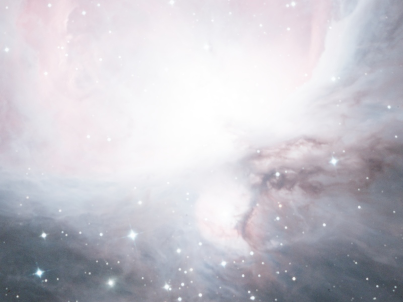
Mouseover: [original image] [scale of 4 pixels, á trous wavelet transform] [scale of 4 pixels, HDRWT]
Figure 1— In this image of the M42 region we can see the third wavelet layer (scale of 4 pixels) extracted with the à trous and HDR wavelet transform algorithms. The wavelet transform is not able to extract structures in the center of the M42 nebula. However, HDRWT can isolate all image structures within the brightest regions without problems.
Processing Example: Messier 101
With original raw data acquired by Jim Misti
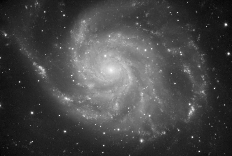
In this example we are going to work with the luminance of a M101 image acquired by Jim Misti, who has kindly allowed us to use it here. Raw data for this one and many other images can be downloaded from Jim Misti's website and form an invaluable source of high-quality working material for the development of image processing techniques and algorithms.
The purpose of this little example is to give an idea of the capabilities and performance of the HDRWT algorithm for processing of deep-sky images. There are advanced parameters in the HDRWaveletTransform implementation that we won't cover here (as layer parameters), and a much more in depth tutorial would be necessary to show the kind of sophisticated (and spectacular) processing techniques that are feasible with HDRWaveletTransform.We'll start after a nonlinear stretch with the HistogramTransform tool, including a midtones balance adjustment to reveal the outermost regions of the galaxy. For this processing example, we have subsampled the image to one half of its original size. The resulting working image can be seen on Figure 2.
You can also download full-size (one half of the original raw data size) versions of the unprocessed and processed images:
Note that the processed image is not intended as a final production work. Besides the need for some noise reduction, it has several defects, as slightly bloated stars and some donought artifacts on bright stars, that would require a more careful procedure. In particular, a star protection mask could be easily generated to avoid all those problems.

Figure 2— The image used for this processing example. The original raw data have been acquired by Jim Misti.
Step 1: First Application of HDRWT
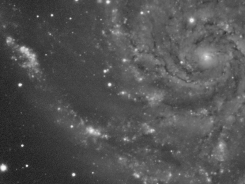
The first step is to reduce the dynamic range on the galaxy. HDRWT works on a prescribed range of scales, and it always starts from the scale of one pixel. In this case, we are going to apply the algorithm up to the scale of 32 pixels, where the most significant structures in the spiral arms are defined. On Figure 3 you can see a brief multiscale analysis that clearly shows this.

Mouseover: [original image] [scale of 32 pixels] [scale of 64 pixels]
Figure 3— The scales of 32 and 64 pixels (wavelet layers # 6 and 7). The scale of 32 pixels contains most of the structures that we are particularly interested in for this processing example.
The Number of layers parameter of the HDRWaveletTransform process will have a value of six, which means that HDRWT will be applied to the scales of 1, 2, 4, 8, 16 and 32 pixels. The 5x5 B3 Spline scaling function will be used because it is good in isolating relatively large structures.
The HDRWT algorithm can work iteratively to converge to a solution where the image is completely flat above the scales where it has been applied. In this case we'll use four iterations.
In addition, we'll enable the Luminance mask option, since we want to apply the algorithm more over the brightest areas of the image. This option will prevent any ringing effect that could originate after several iterations. Figure 4 shows the employed options on the HDRWaveletTransform interface.
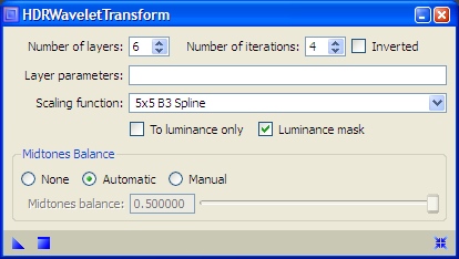
Figure 4— First HDRWaveletTransform parameters.
As a result, the entire spiral structure of the M101 galaxy is shown now much more contrasted. The same happens with small-scale structures that project over bright regions. Figure 5 is a mouseover comparison that can be used to evaluate the result of this first HDRWaveletTransform instance.
Mouseover: [original image] [After HDRWaveletTransform]
Figure 5— First HDRWaveletTransform instance (parameters shown on Figure 4).
Step 2: Second Application of HDRWT
In the next step we'll flatten a bit more the small-scale, high contrast features. To this purpose we'll apply the algorithm to the first three wavelet layers with a single iteration and luminance mask protection (the mask will limit the procedure to very bright, nearly saturated features). These parameters are represented on Figure 6.
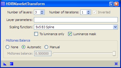
Figure 6— Second HDRWaveletTransform parameters.
This second application has allowed us to reduce the differences in contrast between all galaxy structures, as shown on Figure 7.
Mouseover: [After the first HDRWaveletTransform] [After the second HDRWaveletTransform]
Figure 7— Second HDRWaveletTransform instance (parameters shown on Figure 6). There are some minor problems, as the "donought" effect on a bright star near the upper right corner, that could be very easily corrected with the use of an additional mask. Such mask is out of the scope of this simple processing example.
Step 3: Contrast Enhancement Curve
Thanks to this second HDRWT instance we can enrich our vision of this object: by flattening the image at small scales, a simple curves adjustment can reveal all structures at the same time, from those that were poorly contrasted in the original image, to small features that were close to saturation. The relatively smooth transfer curve that we have applied can be seen on Figure 8.
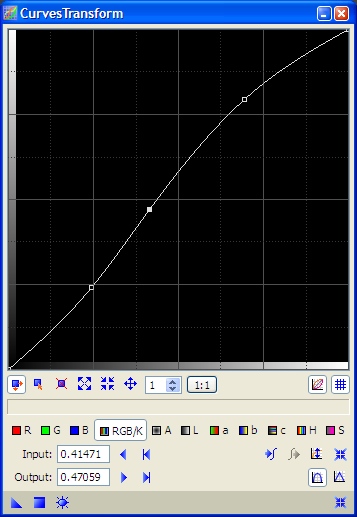
Figure 8— The curve applied after the second HDRWaveletTransform instance.
After applying this curve, the image recovers its lacking contrast (Figures 9 and 10).
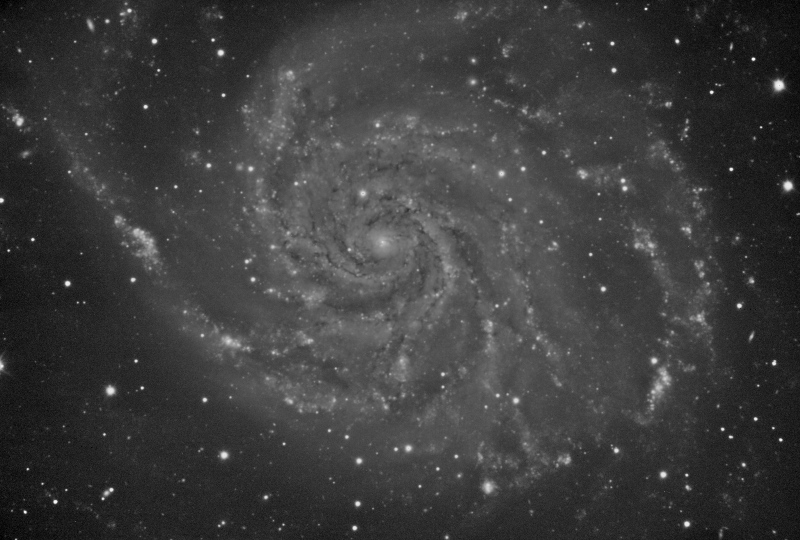
Mouseover: [After the second HDRWaveletTransform] [After applying a contrast enhancement curve]
Figure 9— Contrast enhancement with CurvesTransform (curve points shown on Figure 8).

Mouseover: [After the second HDRWaveletTransform] [After applying a contrast enhancement curve]
Figure 10— Contrast enhancement with CurvesTransform (curve points shown on Figure 8).
The Entire Processing Sequence
The power of the HDRWT algorithm can be better evaluated with the sequence on Figure 11, which summarizes what we have achieved in this processing example.
As we can see, just three very simple steps have been sufficient to obtain a result that before this tool, by employing more traditional techniques, were very difficult to achieve. HDRWaveletTransform is powerful, controllable, and easy to use.

Mouseover: [Original image] [First HDRWaveletTransform] [Second HDRWaveletTransform] [Contrast enhancement curve]
Figure 11— The entire processing sequence.