Master Calibration Frames: Acquisition and Processing
Tutorial by Vicent Peris (PTeam/OAUV/CAHA)
Introduction
Starting from version 1.6, PixInsight includes the standard ImageCalibration (IC) module. This document is a small guide to the acquisition and manual processing procedures necessary to generate master calibration frames optimized for the algorithms implemented in PixInsight.
I highly recommend reading the tooltips on IC's interface, since this guide is an accessory to the IC tool, not a manual to describe its operation and working parameters. IC works only with master calibration frames. This article will guide you on how to obtain them.
Acquisition Notes
As we'll see in this article, the dark scaling algorithm implemented in the IC tool works better when read noise is negligible in the master frames. IC is optimized to work with calibration libraries: don't worry about differing temperatures and exposure times between dark and light frames. IC will always rescale the dark noise to match every light frame.
It is also very important to have a bias library, because thermal noise must be bias-subtracted: only thermal noise must be rescaled in the master dark to match the thermal noise in the light frame.
After experimentation, I highly recommend taking at least 10 dark and bias frames. Never use less bias than dark frames, because this would introduce too much read noise in the bias-subtracted master dark: a 50-frame master dark will have almost all the read noise of a 10-frame master bias.
Don't waste time acquiring dark-flat frames: IC will rescale the master dark to match the dark noise in your flat frames.
Bias and Dark Integration
To generate the master bias and dark frames, we'll use the ImageIntegration module. The same settings will be used in this module for generation of master bias and dark frames. So we'll run the integration twice: first for the bias frames and then again for the dark frames (bias subtraction of dark frames will take place with the IC tool).
There are several important settings to pay attention to:
-
Don't normalize the images, because the bias pedestal must be preserved. Both normalization methods in the Image Integration and Pixel Rejection (1) sections must be disabled (No normalization setting).
-
To be meticulous, the image weighting feature must also be disabled. We want to perform a strict average of a large number of frames, rejecting only clear outliers.
-
To reject possible outliers, I recommend the Winsorized Sigma Clipping algorithm, in case we have a large number of bias and dark frames. A permissive clipping point of 3×sigma can be useful.
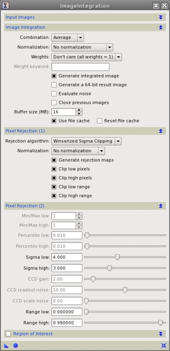
Figure 1— ImageIntegration instance with the right settings to integrate bias and dark frames.
After performing integration of the bias and dark frames, we'll obtain the master bias and master dark frames.
Master Flat Generation (I)
Master flat frame generation is a two-step procedure. First we must calibrate each flat frame with the IC tool. Then we have to integrate the calibrated flat frames to generate the master flat.
Flat frame calibration requires bias and dark subtraction. After selecting our flat frames as target frames in IC, we'll enable the Master Bias and Master Dark sections.
In the Master Dark section, be sure to enable the Optimize checkbox. This will rescale the master-bias-subtracted master dark to fit the thermal noise of each flat frame. Don't worry if your master dark has 1000 seconds of exposure and your flat frame is only 10 seconds: IC will multiply the thermal noise of the master dark by 0.01.

Figure 2— The ImageCalibration tool with the right settings for flat frame calibration.
Master Flat Generation (II)
Once we have calibrated the individual flat frames, we'll integrate them.
After bias and dark subtraction, the flat frames are strictly composed of illumination data. Therefore, we must match the illumination levels of all flat frames. This is the key to do a good flat frame integration.
Illumination fitting is done by multiplying each flat frame to match the average pixel value of all flat frames. This is done by selecting multiplicative normalization in the Image Integration section of ImageIntegration.
Average pixel value fitting is also important to achieve a good rejection of outliers. In the Pixel Rejection (I) section, we'll select the flux equalization option to normalize the frames.
As in the bias and dark frame integration, we'll disable image weighting.
The pixel rejection algorithm to use will depend on the number and type of flats that we have. In the case of sky flats (where we have stars on a highly illuminated sky), or in case of using a small number of flat frames, the best rejection algorithm is percentile clipping. This is the best option to reject the stars.
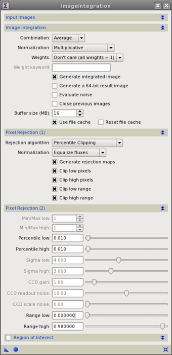
Figure 3— The ImageIntegration tool with the right settings for sky flat integration.
The percentile rejection limits must be very restrictive. Usually we'll set the limits (especially the high limit) below 0.02. Figure 4 shows the rejected high pixel values of a three sky flats frame set. Although a restrictive clipping limit will affect the signal-to-noise ratio of the resulting master flat, this is the only solution to get rid of the stars in all the frames.

Figure 4— Lowering the high limit from 0.05 to 0.01 will reject random pixels in the image, but it will reject better the star trail crossing the field of view. The mouse over links below show the corresponding rejection maps.
Mouse over:
4a— Flat frame with star trail.
4b— 0.050 high percentile limit.
4c— 0.030 high percentile limit.
4d— 0.020 high percentile limit.
The effect of lowering the rejection limit is clearly visible on Figure 5. A high limit value of 0.05 leaves the outer regions of the star trail. With a 0.01 high limit, only the fainter star trail is barely visible.
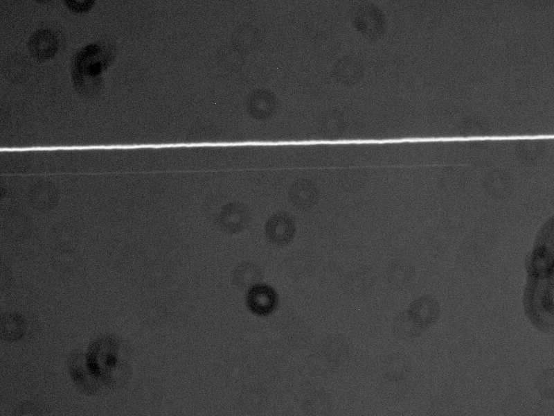
Figure 5— The master flat frame.
Mouse over:
5a— Flat frame with star trail.
If we acquire a large number of dome or box flats (flats without stars), outlier rejection is rather simple. Winsorized sigma clipping with permissive rejection limits will do a fine job.
Now we have our master flat frame and will use it in the IC tool to calibrate the light frames. Just remember to disable the Calibrate checkbox in the Master Flat section, as we already have calibrated our master flat frame.
Dark Frame Scaling Considerations
The thermal noise scaling algorithm optimizes the master dark frame for a minimum amount of noise in the resulting calibrated frame. We should take into account several considerations.
Dark frame scaling is convenient even for temperature-regulated cameras. The algorithm will correct the small temperature oscillations of the camera during light frame acquisition. Figure 6 shows the benefit of activating dark frame scaling for a temperature-regulated light frame.
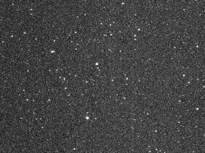
Figure 6— Thermal noise scaling in action. Master bias is composed of 90 bias frames, and master dark is composed of 45 dark frames. Camera temperature was set to –10°C; target light frame temperature was –10.1°C.
Mouse over:
6a— Original uncalibrated image.
In this example, by disabling the dark frame scaling the calibrated image shows a thermal noise over correction. This can be easily seen as dark pixels over some of the stars. When we enable dark frame scaling, some hot pixels remain in the calibrated image, but they will be rejected in the light image integration process.
It is important to acquire a large number of bias and dark frames. Figure 7 shows the effect of using low-signal bias and dark frames.
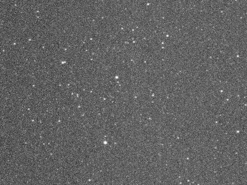
Figure 7— Low-quality bias and dark masters lead to under correction of thermal noise.
Mouse over:
7a— Original uncalibrated image.
7b— Using 3 bias and flat frames.
The lower the quality of the masters we have, the poorer the thermal noise correction that we'll achieve. This is due to a significant presence of read noise in the master dark frame. As the scaling algorithm minimizes noise in the calibrated image, thermal noise must be under-corrected to compensate for the addition of read noise to the calibrated image. Although we can see some hot pixels, the poorly calibrated images represent the minimum-noise solution that can be achieved with the use of low-quality masters. High signal-to-noise ratio masters tend to reduce the presence of hot pixels, as shown on Figure 7.
Conclusion
PixInsight's tools usually require different acquisition and processing methods. Although we will have a master frame generation tool in the near future, the ImageCalibration tool works better with the acquisition methodology that we have described. The same methodology will be necessary with the future master frame generation tool.