Keeping terminology discussions aside for a while, here is a detailed description of our dark frame optimization algorithm.
Let's state the problem first. We may describe an uncalibrated raw light frame with this very simple equation:
I = I0 + D + B
where I is the uncalibrated raw light frame, D is the dark current, and B is the bias pedestal. All terms in this equation are vectors (or matrices) because we are describing a process for a whole image at the pixel level. I
0 is the dark-and-bias-subtracted raw light frame (we know that the next calibration step would be flat fielding, but this is unimportant to this discussion). Our goal here is to obtain I
0.
As we have stated it above, this is a trivial problem: just subtract good master bias and dark frames from the uncalibrated light frame, and the result will be a good approximation to I
0 (the better the masters, the better the approximation). However, the actual problem is more complex because the dark current D is highly time- and temperature-dependent, so a perfect match between the dark current signals in I and D is only a theoretical goal. A better (but still far from perfect) approximation to the actual problem is more like this:
I = I0 + k*D + B
where k is a scaling factor that attempts to account for effective exposure time and temperature differences between the light frame and the master dark frame. The process of finding a good approximation to the scaling factor k is what we call
dark frame optimization.
Note that I have said that this is far from a perfect solution. It is wrong mainly because the dark current does not vary linearly with exposure time and temperature for the whole numeric range of the data, so a single multiplicative factor cannot be very accurate, especially when time and temperature differences between I and D are large. Dark optimization, however, is
always better than nothing. From our experience, dark optimization is beneficial even if exposure times and temperatures are matched between light and dark frames. For this reason the corresponding parameter is enabled by default in our ImageCalibration tool.
Now that we have described the problem, let's describe our solution. Algorithmically this is known as an
optimization problem: find the value of a parameter that minimizes (or maximizes) the value of a function. For example, think in terms of the economical cost of a production process. We have to produce an item A that depends on a factor r, which leads to the problem:
find the value of r that minimizes the cost of producing A. In real cases r usually represents a complex set of parameters and constraints, such as environmental factors, availability of prime matters, production systems, etc., so that the most difficult part of the solution often consists of identifying a significant set of parameters or model to define a suitable
cost function. This leads to the subject of
linear programming.
The dark frame optimization problem is a relatively simple case of function optimization with a single parameter. The first step is to define the cost function that we want to minimize. To explain why and how we have selected a particular function we need some visual analysis. Take a look at the following two images:
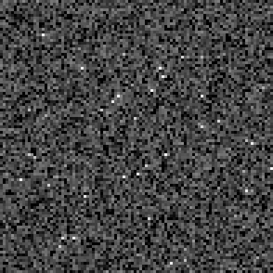
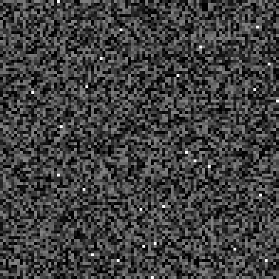
One of them is a crop of a bias-subtracted master dark frame, the other is not. Difficult to say which is which, isn't it? The image to the right is a mix of synthetically generated uniform noise and impulsional noise (salt and pepper noise) with 0.5% probability. It has been generated with the NoiseGenerator tool in PixInsight. With this comparison I am trying to show that a master dark frame looks very similar to random noise: essentially, a master dark frame is composed of pixel-to-pixel intensity variations whose spatial distribution is rather uniform, plus a relatively small amount of hot pixels whose distribution and typical values are similar to impulsional noise. Of course, we know that the thermal noise is a
fixed pattern characteristic of a given sensor, so it is not random because it is predictable. However,
morphologically a master dark frame is virtually indistinguishable from random noise. It is not noise, but it behaves like that, and we are going to take advantage of this simple property to implement a purely numerical solution.
So our cost function is just a noise evaluation function. We already have implemented a powerful multiscale noise evaluation algorithm in several PixInsight tools, such as ImageIntegration, to implement a noise-based image weighting algorithm (Jean-Luc Starck and Fionn Murtagh,
Automatic Noise Estimation from the Multiresolution Support, Publications of the Royal Astronomical Society of the Pacific, vol. 110, February 1998, pp. 193-199). In this case, however, we have implemented a simpler and very efficient method (Jean-Luc Starck and Fionn Murtagh,
Astronomical Image and Data Analysis, Springer-Verlag, 2002, pp. 37-38) known as
k-sigma noise estimation:
- Compute a single-layer wavelet transform of the image. This transform consists of the finest wavelet scale w
1 plus a residual c
J, which we simply discard. We use the standard B3 spline wavelet scaling function as a separable low-pass filter.
- Iterate a k-sigma process as follows: At each iteration n > 0, denote by d(n) the subset of pixels in w
1 such that |d(n-1)
ij| < k*sigma(n-1), where sigma(n-1) is the standard deviation of the current subset of pixels (from the previous iteration). In our implementation we have d(0)=w
1, k=3, and this process is iterated until no significant difference is achieved between two consecutive iterations. For dark frame optimization, we iterate up to 1% accuracy and normally 3 or 5 iterations are sufficient.
- The final noise estimate is the standard deviation of the resulting subset of pixels. Note that this is an
unscaled noise estimate of Gaussian white noise, since it depends on the wavelet scaling function used. However, since we don't want to compare noise estimates among different images, but only to minimize the noise in a particular image after dark subtraction, an unscaled estimate is perfectly suitable.
Note that the use of a wavelet transform is actually irrelevant in this process; we use it just because it is very fast and we have it readily available on the PixInsight/PCL platform. A simple convolution with a low-pass filter followed by a subtraction from the original image would be equivalent.
This noise evaluation algorithm is robust and 'cannot fail' The rest of our algorithm is a routine to find the minimum of a unimodal function. For the sake of robustness, I haven't implemented anything fancy here: just an adaptation of the classical
golden section search algorithm. Perhaps not the fastest alternative, but golden section search is absolutely robust, which is what I want here.
Summarizing, the algorithm can be described at a high level as follows:
- Find a range [k
0,k
1] of dark scaling factors that bracket the minimum of the noise evaluation function. This is the
initial bracketing phase.
- Iterate the golden section search algorithm to find the minimum of the noise evaluation function. At each iteration, compute the calibrated raw frame as:
I0 = I - k*D - B
and evaluate the noise in I
0 with the k-sigma iterative method.
- Iterate until the minimum of the noise evaluation function is determined up to a prescribed accuracy (1/1000 fractional accuracy in our implementation).
- The final value of the dark scaling factor is the value of k from the last iteration.
From our tests, this algorithm has proven extremely robust and accurate. However it has two known problems:
- It is very sensitive to bad quality calibration frames. In particular, if the master bias and/or the master dark frames include significant amounts of read noise, the optimization algorithm will find a value of k that
overcorrects thermal noise to compensate for the additive random noise component. In extreme cases, this may lead to
dark holes as a result of overcorrected hot pixels. However, if the master calibration frames are bad quality ones, the whole image reduction process makes no sense, actually...
- It implicitly assumes that the dark optimization function is constant for the whole range of numerical data values, since it consists of a simple multiplicative factor. This is not the case in practice, especially for high intensity values. As a result of this simplistic optimization model, the algorithm tends to undercorrect hot pixels. This is a very minor issue, however, since hot pixels are easily rejected during integration (because you dither your images, don't you?) and can be removed also with cosmetic correction techniques.
In a future version of the dark optimization algorithm we'll compute different optimization factors for separate intensity ranges in a spline fashion. This should fix the hot pixel undercorrection problem.


